


-32- G0486/G0487 Wide Belt Sander
To adjust the table parallelism:
1. Pass the widest size board your machine will
allow through the sander until the
entire sur-
face of the board is making contact with the
sanding belt.
2. Measure the thickness of the board at vari-
ous points around the edge.
3. If there is a variation of thickness, the table
can be adjusted accordingly.
4. DISCONNECT THE SANDER FROM THE
POWER SOURCE!
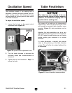
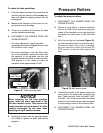
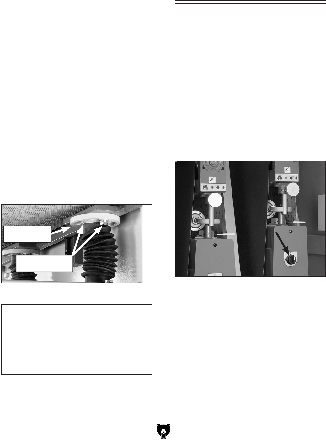
—For minor adjustment, loosen the table
mounting bolts shown in
Figure 32 and rotate
the elevation screw flange.
—For major adjustment, mark the chain loca-
tion on all sprockets, remove the chain from
the sprocket to be adjusted, and turn the
sprocket counterclockwise to raise the table.
One quarter of a turn raises or lowers an
elevation screw approximately 0.020"
5. Reinstall the chain onto the sprocket adjust-
ed in
Step 4, tighten the bolts, and test the
machine.
To adjust the pressure rollers:
1. DISCONNECT THE SANDER FROM THE
POWER SOURCE!
2. Plane a 6' long 2x4 to a uniform thickness
and cut it in half. Place one board along the
length of the feed belt on the right-hand side
and place the other board on the left-hand
side.
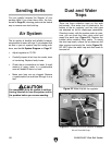
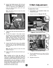
3. With the sanding belt tensioned (Figure 33),
move the sanding rollers by hand and
manu-
ally raise the table until you hear the sandpa
-
per just contact the surface of the wood. DO
NOT continue to raise the table beyond that
point.
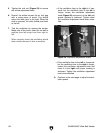
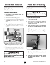
Pressure Rollers
4. Connect the sander to the power source and
make note of the reading on the digital dis
-
play. Then manually lower the table 0.020"
to 0.030". This is how much lower the infeed
pressure roller should be set when compared
to the sanding surface of the sanding roller.
5. DISCONNECT THE SANDER FROM THE
POWER SOURCE!
Figure 33. Belt tension knob.
NOTICE
When adjusting the left front elevation
screw, make the same adjustment to the
left rear elevation screw. This ensures the
height from the front to the back of the table
remains unchanged. Do the same when
adjusting the right elevation screws.
Figure 32. Table mounting bolts.
Table Mounting
Bolt
Elevation
Screw Flange