


4.
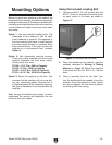
Figure 7
5.
Step 4
6. Step 3
SECTION 8: WIRING
Page 45
7. Figures 4
5
8.
Step 7
9. Step 7
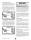
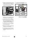
Figure 7. Contactor release tab location.
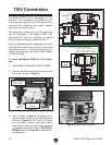
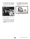
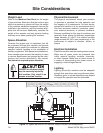
Hot
Hot
Ground
6-20 Plug
220
VAC
Ground
Neutral
Hot
Ground
L5-30 Plug
(As Recommended)
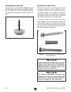
PE
V2
V1
U2
U1
U2
V1
V2
Z1
W1
Z2
W2
U1
U2
V1
V2
Z1
W1
Z2
W2
U1
To Electrical Box
Start
Capacitor
150 MFD
250 VAC
Run
Capacitor
20 MFD
450 VAC
110V Terminal
Block Jumper
Position.
(Wire positions
are the same for
110V/220V)
To Electrical Box
Cord Rewired for 110V
Motor 220V
Figure 8. Jumper positions on terminal block.
10.
Figure 8