


G1028Z/G1029Z Dust Collector
-21-
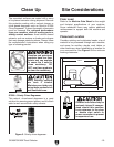
Determining Main Line Duct Size
The general rule of thumb for a main line duct is
that the velocity of the airflow must not fall below
3500 FPM.
For small/medium sized shops, using the inlet
size of the dust collector as the main line duct
size will usually keep the air velocity above 3500
FPM and, depending on your system, will allow
you to keep multiple branches open at one time.
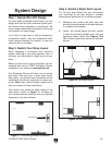
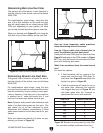
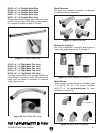
Mark your drawing as in Figure 23, but using the
inlet size for your dust collector as the main line.
Figure 23. Main line size labeled on sketch.
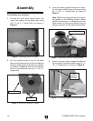
Determining Branch Line Duct Size
The general rule of thumb for a branch line duct is
that the velocity of the airflow must not fall below
4000 FPM.
For small/medium sized shops, using the dust
port size from the machine as the branch line duct
size will achieve the correct velocity in most appli-
cations. However, if the dust port on the machine
is smaller than 4", make the branch line 4" and
neck the line down right before the dust port.
Note: Systems with powerful dust collectors work
better if multiple blast gates are left open. This
also allows you to run two machines at once.
Experiment with different combinations of blast
gates open/closed to find the best results for your
system.
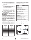
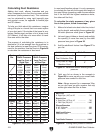
Write your determined branch line sizes on your
drawing, as shown in Figure 24
.
Figure 24. Branch line sizes labeled on sketch.
6''
5''
4''
4''
4''
4''
4''
Here are some frequently asked questions
when determining branch line sizes:
How do I figure which size of branch line to
use if the machine has two dust ports?
Simply add the total CFM given for each size from
Figure 20 and refer to that CFM number to Figure
25. Then, split the branch line just before the dust
ports with matching duct sizes.
What if two machines share the same branch
line?
You have two options:
1. If both machines will be running at the
same time, add the total CFM given for
each size from Figure 20 and match the
branch line given in Figure 25
.
2. If both the machines will never be run at
the same time, reference the machine
with biggest dust port to Figure 25 and
add blast gates after the Y-branch to
open/close the line to each machine.
Total CFM Branch Line Size
400 4"
500 4"
600 5"
700 5"
800 6"
900 6"
1000 6"
Figure 25. Branch line sizing chart by total CFM
(for use when multiple machines share line).