


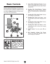


Basic Controls
Figure 5
A. Upper Roller Adjustment Screws:
B. Sanding Belt Quick-Release Tension
Lever:
C. Sanding Belt Table Angle Scale:
D. Sanding Belt Table Lock Lever:
E. Sanding Disc Table Angle Scale:
F. Sanding Disc Table Lock Knob (1 of 2):
G. ON/OFF Switch: ON
OFF
H. Belt Assembly Locking Cap Screw:
Figure 5.
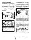
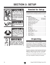
To reduce the risk of
serious injury when using
this machine, read and
understand this entire
manual before beginning
any operations.