


- 10 - Grizzly Imports, Inc. G3690
IX. MAINTENANCE
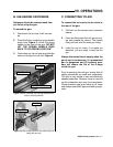
B. DAMAGED DRIVER
To remove the driver:
1. Disconnect gun from the air supply and
remove any fasteners from the maga-
zine.
2. Loosen the 4 cap screws securing the
gun cap to the gun body sequentially.
3. Remove the four cap screws and the gun
cap and place them to one side.
4. With your fingers, reach into the air cylin-
der, grasp the main piston, and pull out
the driver.
5. Inspect driver condition and repair or
replace as necessary. Replacement dri-
vers are sold pre-attached to the main
piston and are referred to as the “com-
plete driver unit”.
C. O-RINGS AND RE-ASSEMBLY
Since the gun is disassembled, inspect the
condition of the visible O-rings. If the O-rings
show signs of wear and tear, they should be
replaced. Inspect the surfaces where the O-
rings seal for any possible rough spots which
will erode the new O-rings. When replacing
the O-rings, make sure that there is no dirt or
grit in the groove where the O-rings seat. Do
not stretch the O-rings or nick them on any
sharp edges or burrs. If cleaning parts with a
solvent, do not use a solvent that may deteri-
orate the O-rings.
To re-assemble the gun:
1. Before replacing O-rings, lubricate them
with a light grease that is non corrosive to
rubber.
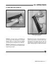
2. IMPORTANT: Carefully position the dri-
ver tip into the plastic driver insert from
the top of the nail gun. You may have to
wiggle the driver so the main piston seats
into the cylinder. The driver has a T-
shaped cross section and will only fit one
way. If the driver is not seating, do not
force it. Remove the driver unit, rotate
180°, and try to reinstall it.
3. Replace the cap on top of the gun.
Tighten the cap screws sequentially. If
the cap screws are not tightened even-
ly, the cap will not seat correctly, air
will leak, and the gun will not function.
Ensure that the washers are installed
under the cap screw heads.
4. Re-check all bolts to make sure they are
tight and test the gun to ensure that it
works properly. See the following para-
graph.
NOTE: Before putting the gun back together,
read through Section IX.C.
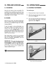
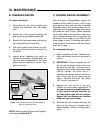
Gun Cap
Cap Screws
Driver
Main Piston
Air Cylinder
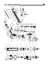
Figure 11 shows the gun partially disassembled to
repair or replace the driver.