


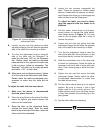
-28- Extreme Duty Planers
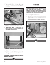
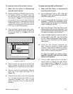
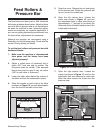
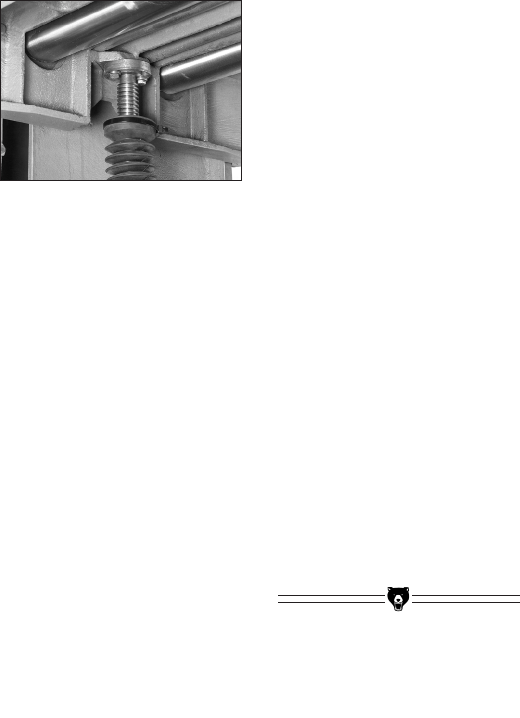
Figure 14. Column adjustment flange
underneath table.
4. Locate the two columns underneath the
table. These are covered in flexible rubber
sleeves. Underneath the sleeves are adjust-
ment
flanges that allow you to disengage the
table columns from the lifting gears.
To
adjust the table, you need to disen-
gage the opposite side that needs to be
adjusted.
5. Pull the rubber sleeve down on the deter-
mined
column to expose the table adjust-
ment
flange shown in Figure 14. You may
need to cut the plastic cable tie in order to
remove the sleeve.
6. Loosen the two nuts that secure the table
adjustment
flange; this will allow the opposite
side of the table to be moved up or down.
7. Turn the fine adjustment knob to raise the
side
of the table with the wood block, so the
wood block barely touches the cutterhead.
8. Slide the wood block over to the other side
to
check for consistency. Adjust the table as
necessary until each side is even with each
other. Use a feeler gauge to check the toler-
ances.
9. Tighten the two nuts that secure the table
adjustment
flange. Double check the table-
to-cutterhead measurement to make sure
the table did not move.
10. Pull the rubber sleeve back up to its original
position.
Be sure to secure it with a new
plastic cable tie if you cut the old one. The
rubber sleeves must cover the lifting column
to keep fine sawdust from building up in the
gear grease.
11. Set the table rollers as necessary.
8. Loosen the two nuts that secure the table
adjustment flange; this will allow the opposite
side of the table to be moved up or down.
9. Turn the fine adjustment knob to raise the
side
of the table with the Rotacator
®
to
make the dial read .050" on the Rotacator
dial. Double check the table-to-cutterhead
measurement on the right end to make sure
it did not move. Adjust as necessary. The
Rotacator
®
will allow you to easily get each
end within ±.001" of each other.
10. When each end is adjusted properly, tighten
all
of the nuts at the table mount and clamp.
Double check the table-to-cutterhead mea-
surement
to make sure the table did not
move.
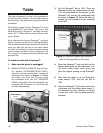
To adjust the table with the wood block:
1. Make
sure the planer is disconnected
from the power source!
2. Place the wood block on the side of the table
where
the tightest gap exists between the
table and the cutterhead.
3. Raise the table so the cutterhead barely
touches
the wood block. Slide the wood
block to the other side of the table, under the
other end of the cutterhead.