-22-
G9749 Variable Speed Drill Press
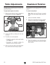
2. Unlock the table by rotating the lock lever
clockwise.
3. The table can now be adjusted:
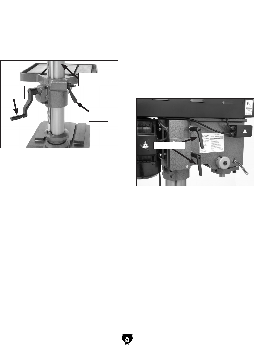
— Vertically by using the table crank handle
(see Figure 19).
— Horizontally by manually rotating the
assembly around the center column.
4. When you have the table in the desired posi-
tion, use the lock lever to keep in place.
Table Adjustments
The table can be raised/lowered and rotated 360º
around the column.
To adjust table height and rotation:
1. Make sure the table lock lever is mounted on
the locking nut as shown in
Figure 19.
The headstock can be adjusted 360º around the
column.
To rotate the headstock:
Note: Make sure the drill press is properly
bolted to the floor before doing this proce
-
dure.
1. UNPLUG THE DRILL PRESS!
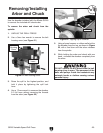
2. Rotate the two headstock lock levers counter-
clockwise to loosen them (see
Figure 20).
3. Rotate the headstock to the desired position
and use the lock levers to secure the head
-
stock in place.
Headstock Rotation
Figure 19. Table crank handle and lock lever.
Center
Column
Lock
Lever
Crank
Handle
Figure 20. Headstock lock levers.
Lock Levers


