


-2-
H8370 Power Feed for Mill/Drills
Functional Overview
The Model H8370 power feed is designed to
install on the left side of a mill/drill table to pro
-
vide powered longitudinal movement of the table.
Refer to Figures
2–3 and the descriptions below
to become familiar with the functional parts of the
power feed system.
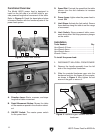
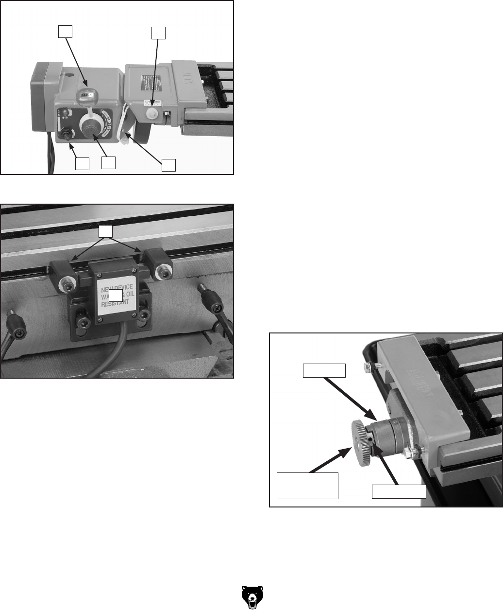
Figure 2. Power feed controls.
E
A
B
D
C
Figure 3. Limit switch and stops.
G
F
A. Direction Lever: Starts, reverses, and stops
longitudinal table movement.
B. Rapid Movement Button: Moves the table
at the maximum speed in the direction select
-
ed.
C. ON/OFF Switch: The master power switch
for the power feed.
D. Speed Dial: Controls the speed that the table
moves—turn the dial clockwise to increase
the speed.
E. Power Lamp: Lights when the power feed is
turned ON.
F. Limit Stops: Activate the limit switch. Secure
these devices along the table to set the range
of movement.
G. Limit Switch: Stops powered table move
-
ment when either limit stop presses a plunger
on the switch.
Installation
Tools Needed Qty
Hex Wrench 2.5mm ...........................................
1
Hex Wrench 5mm ..............................................
1
Hex Wrench 6mm ..............................................
1
Wrench 12mm ...................................................
1
To install the power feed:
1. DISCONNECT MILL/DRILL FROM POWER!
2. Remove the handle assembly from the left
side of the longitudinal leadscrew.
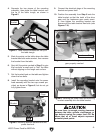
3. Slide the provided leadscrew gear onto the
leadscrew and into the fingers of the coupler,
as shown in
Figure 4, then tighten the set
screw of the gear to secure it.
Figure 4. Leadscrew gear installed onto the
leadscrew.
Coupler
Leadscrew
Gear
Set Screw