


H8370 Power Feed for Mill/Drills
-3-
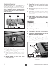
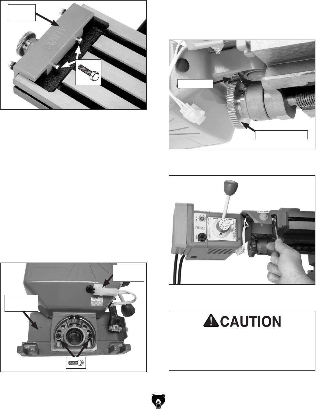
4. Separate the two pieces of the mounting
assembly, then place the table bracket over
the lip of the table trough, as shown in
Figure 5.
Figure 5. Table bracket mounted on the lip of
the table trough.
Table
Bracket
5. Mark the points on the table where the table
bracket hex bolts make contact, then remove
the bracket from the table.
6. Spot drill the points marked in Step 5 to give
the hex bolts a small spot to "bite" the table
without slipping on the rough cast surface.
7. Set the bracket back on the table and tighten
down the hex bolts.
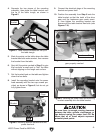
8. Install the mounting bracket onto the power
feed assembly with the two cap screws pro
-
vided, as shown in
Figure 6, but do not yet
fully tighten them.
9. Connect the electrical plugs of the mounting
bracket and power feed.
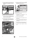
10. Position the assembly from Step 8 onto the
table bracket so that the teeth of the drive
gear and the leadscrew gear mesh exact
-
ly, then tighten the mounting bracket cap
screws and the table bracket hex bolts (see
Figures 7–8).
Figure 7. Power feed drive gear and leadscrew
gear properly meshed.
Drive Gear
Leadscrew Gear
Figure 8. Installing the power feed and mounting
bracket assembly onto the table bracket.
Figure 6. Mounting bracket installed onto the
power feed unit.
Mounting
Bracket
Electrical
Plugs
Be sure there is enough running clearance
between the table, spindle, vise/clamps, or
jigs before turning the power feed ON. Be
aware that all of these objects represent
potential pinch points.