


Page 12SKU 3733 For technical questions, please call 1-800-444-3353.
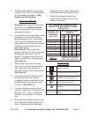
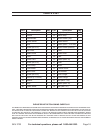
SPECIFICATIONS
Blade Diameter
(Blade Not Included,
Sold Separately)
4"
(67113 4” Continuous
Rim Diamond Blade
Recommended)
Arbor Diameter 5/8"
Maximum Cutting
Capacity
1-1/16”
Electrical Requirements 120 V~ / 60 Hz
Tilting Head 22.5° to 45° Bevel
Blade Rated Speed 4480 RPM
UNPACKING
When unpacking, check to make sure
that the item is intact and undamaged. If
any parts are missing or broken, please
call Harbor Freight Tools at the number
shown on the cover of this manual as soon
as possible.
INSTRUCTIONS FOR
PUTTING INTO USE
Read the ENTIRE IMPORTANT
SAFETY INFORMATION section
at the beginning of this manual
including all text under
subheadings therein before set
up or use of this product.
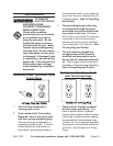
TO PREVENT
SERIOUS INJURY
FROM ACCIDENTAL
OPERATION:
Turn the Power Switch of the
tool to its “OFF” position and
unplug the tool from its
electrical outlet before
assembling or making any
adjustments to the tool.
Note: The Tile Saw features a built-in
water supply that keeps its Tile Saw
Blade cool, reduces dust and debris,
and is easy to clean. Its efcient
design returns water directly to the
reservoir and is accurate enough for
most ceramic tile, quarry tile, marble,
terra cotta, and slate jobs.
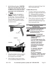
ASSEMBLY
To Install The 4” Diamond Tile Saw
Blade:
WARNING! Make sure the Power 1.
Switch (4) of the Tile Saw is in its
“OFF” position and its Power Cord
(11) is unplugged from the electri-
cal outlet prior to performing any
assembly.
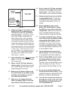
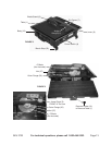
Remove the Screw (16) that holds 2.
the Table (1) in place and left the
Table until the three catches at its
midsection clear the Table’s under-
side. Then remove table complete-
lyh. (See Figure 2, next page.)
Remove the Nut (37) attached to the 3.
Motor (32) arbor. Then remove the
Outer Flange (36). See Figure 3,
next page.)
WARNING! Install Blade (67113 4” 4.
Continuous Rim Diamond Blade
is sold separately) with directional
arrow visible from Water Tray side.
Slide Blade in and up from the under-
side slot in the Table, then over arbor
and rear hub ange. (See Figure 3.)
Attach Outer Flange and secure Nut 5.
over arbor. Turn Nut clockwise until
tight. Do not overtighten. (See Fig-
ure 3.)
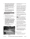
Disconnect Guard Stand (24) from 6.
Guard Assembly. Slide Stand’s
unthreaded end through slot under