


Page 9For technical questions, please call 1-800-444-3353.Item 38142
Operating Instructions
Read the ENTIRE IMPORTANT SAFETY INFORMATION section at the beginning of this
manual including all text under subheadings therein before set up or use of this product.
Tool Set Up
TO PREVENT SERIOUS INJURY FROM ACCIDENTAL OPERATION:
Turn the Power Switch of the tool off and unplug the tool from its electrical
outlet before performing any procedure in this section.
TO PREVENT SERIOUS INJURY: DO NOT OPERATE WITH ANY GUARD DISABLED,
DAMAGED, OR REMOVED. Moving guards must move freely and close instantly.
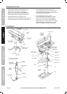
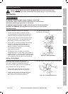
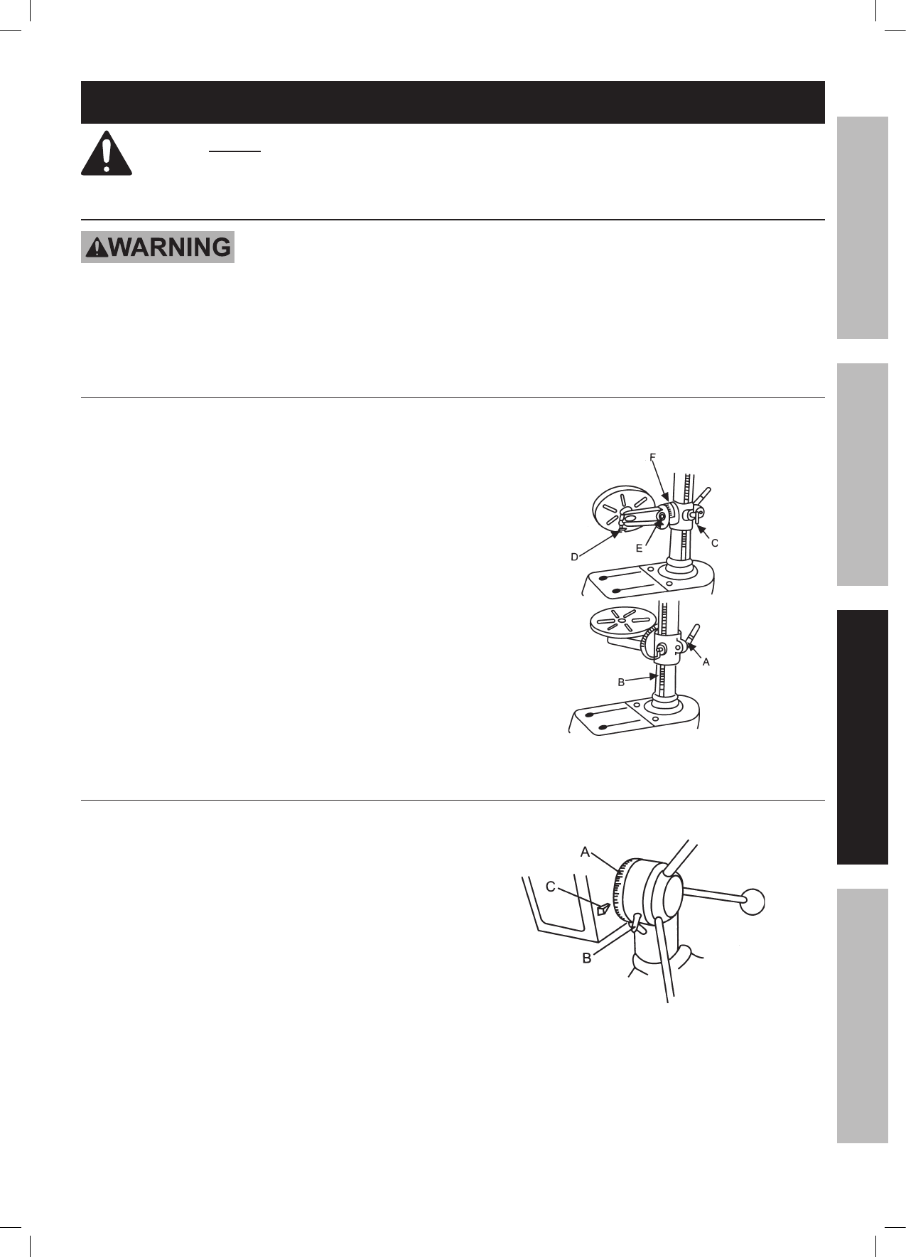
Table Adjustment
The table is capable of moving in four directions.
1. Raise or lower the table by slackening off the
arm locking handle (A) and turning the crank (C),
clockwise to raise and counterclockwise to lower.
2. Swivel the table about the column by slackening off
the arm locking handle. The table assembly, arm
and rack (B), move as one around the column.
3. Tilt the table by slackening the Bevel Table Locking
Screw (E), and tilting to the required angle.
A scale (F) is provided on the arm measured in
degrees, to assist in setting the required angle.
For all normal operations the
table should be set at 0°.
4. TO ENSURE THAT THE DRILL IS ENTIRELY
PERPENDICULAR TO THE TABLE, insert a piece of
straight round bar in the chuck, place a square on the
table and bring it up to the round bar. Adjust the table
tilt if necessary so that the table is correctly aligned.
5. Turn the table about its axis,
by slackening off clamp (D).
Figure A: Table Adjustment
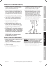
Setting a Drilling Depth
Located around the Spindle Feed Shaft is a
Depth Stop Collar (A) carrying a graduated scale.
The collar is capable of turning about the shaft,
and may be locked in place by a Locking Screw (B).
The graduations are in inches and metric.
1. Lower the drill (with the power OFF) so that it
contacts the material and hold in that position.
2. Slacken off the locking screw and turn the collar
so that the measurement for the depth of the
hole required is in line with the pointer (C).
3. Lock the collar in this position using the locking screw.
Figure B: Drill Depth Adjustment
SAFETYOPERATIONMAINTENANCE SETUP