


Page 7SKU 44991
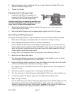
2. Adjust the position of the Limit Block (65) up or down. Refer to the Ruler (67) on the
side of the Vertical Support (68).
3. Tighten the Handle.
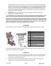
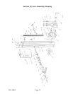
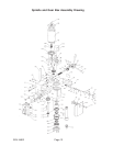
Adjusting the Vertical Support Angle
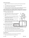
1. Using the Large Wrench (accessory A),
loosen Lock Nut (70) only enough to allow
movement of the Vertical Support (68).
Caution: Avoid injury or damaging machine, hold
the Vertical Support in place to keep it from fall-
ing to the left or right during adjustment.
2. Adjust the Vertical Support angle as needed (45 degrees left or right, maximum).
Check Ruler (44) for angle.
3. When the Vertical Support is at the desired angle, tighten Lock Nut (70) again.
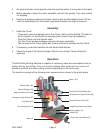
Basic Drilling and Milling Procedure
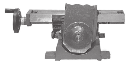
During the following procedure, it may be helpful to refer to the machine photo on page 5.
1. Make desired changes and adjustments to the machine for drilling or milling.
2. Set an appropriate speed for drilling or milling the workpiece.
Use the Speed Control Knob (134) to adjust the Spindle speed. For cutting metal, the
speed range should be between 200 to 2500 RPM. Faster speeds are generally used
when milling softer materials and drilling small holes; And slower speeds for milling
harder material and drilling larger holes.
3. Using a fixture (not supplied) mount the workpiece to the Working Table (19).
4. Adjust the Limit Block (65) height.
This will enable Spindle movement to the desired cut, and disable an over cut which
could damage the workpiece fixture or Work Table.
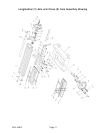
5. Adjust the Working Table Longitudinal Feed Hand Wheel (X-Axis) and the Cross Feed
(Y-Axis) Hand Wheel (5) into position for milling or drilling.
One step turn of the Hand Wheel moves the Work Table 0.03 mm; one complete turn
moves it 1.5 mm.
6. Remove any tools or obstacles from in and around the Work Table.
7. Turn the machine on. Lift the Emergency Stop Switch (137) cover, and pull button out.
8. If necessary, adjust the Spindle speed with the Speed Control Knob (134).
9. Begin milling or drilling.
Use the Operating Lever (58) to make large adjustments to the Spindle height. For fine
adjustments, use the Fine Feeding Wheel (93). Refer to the ruler on the Vertical
Support to determine drilling or milling depth. Caution: Keep hands and fingers clear
of the working table and workpiece while the machine is in operation.
(68)
(70)