


SKU 47065 For technical questions, please call 1-800-444-3353. PAGE 7
8. NOTE: With the Air Compressor turned on, the operation is automatic and under the
control of the automatic switches inside the box under the Power Switch (1A).
NEVER open the power switch box or adjust the controls within.
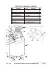
To Adjust The Air Output To The Pneumatic Tool:
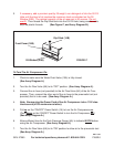
1. NOTE: When adjusting the air pressure being forwarded to the pneumatic tool, you
will need to compare the pressure readings of both the Tank Pressure Gauge (3A)
and the Tool Pressure Gauge (4A). The reading on the Tank Pressure Gauge dic-
tates the maximum/minimum air pressure at which the Tool Pressure Gauge may
also be set. (See Assy. Diagram A.)
2. With the Air Compressor running, and the air hose and pneumatic tool hooked up to
the Air Compressor, pull up on the Tool Pressure Adjuster (2A). Turn the Tool Pres-
sure Adjuster
clockwise to increase the air output to the tool, up to the working air
pressure (115 PSI) as indicated on the Tank Pressure Gauge (3A). (See Assy.
Diagram A.)
3. Turn the Tool Pressure Adjuster (2A)
counterclockwise to decrease the air output
to the tool, down to the minimum rated pressure (0 PSI) as indicated on the Tank
Pressure Gauge (3A). (See Assy. Diagram.)
To Use The Tank Pressure Relief Valve:
1. The Tank Pressure Relief Valve Ring (5A) is used when decompression is needed
quickly and efficiently. (See Assy. Diagram A.)
2. To decompress the Air Tank (9A) pressure, press the “ON/OFF” Power Switch (1A)
down to turn off the Air Compressor. (See Assy. Diagram A.)
3. Pull out on the Tank Pressure Relief Valve Ring (5A) to immediately release air
pressure in the Air Tank (9A). (See Assy. Diagram A.)
To Empty Air And Condensation From The Tank:
1. The Water Drain Valve (10A) is located underneath the Air Tank (9A), and should be
used daily to release all trapped moisture through this valve. The Water Drain Valve
will also eliminate condensation that may cause Air Tank corrosion. (See Assy.
Diagram A.)
2.
WARNING: Do not open the Water Drain Valve (10A) so that more than four
threads are showing.
3. Push down on the “ON/OFF” Power Switch (1A) to turn off the Air Compressor. Then,
unplug the Air Compressor’s Power Cord from the electrical outlet. (See Assy. Dia-
gram A.)
4. Slowly and carefully unscrew (no more than four threads) the Water Drain Valve
(10A) until the compressed air and condensation begins to be released from the Air
Tank (9A). Allow sufficient time for all of the air and condensation to escape from
the Air Tank. Then, firmly retighten the Water Drain Valve. (See Assy. Diagram A.)
REV 01/05; 08/05