


Page 8 For technical questions, please call 1-800-444-3353. Item 60238
Operating Instructions
Read the ENTIRE IMPORTANT SAFETY INFORMATION section at the beginning of this
manual including all text under subheadings therein before set up or use of this product.
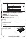
Tool Set Up
TO PREVENT SERIOUS INJURY FROM ACCIDENTAL OPERATION:
Turn the Power Switch of the tool off and unplug the tool from its electrical
outlet before performing any procedure in this section.
TO PREVENT SERIOUS INJURY:
DO NOT OPERATE WITH ANY GUARD DISABLED, DAMAGED, OR REMOVED.
Moving guards must move freely and close instantly.
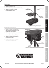
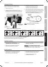
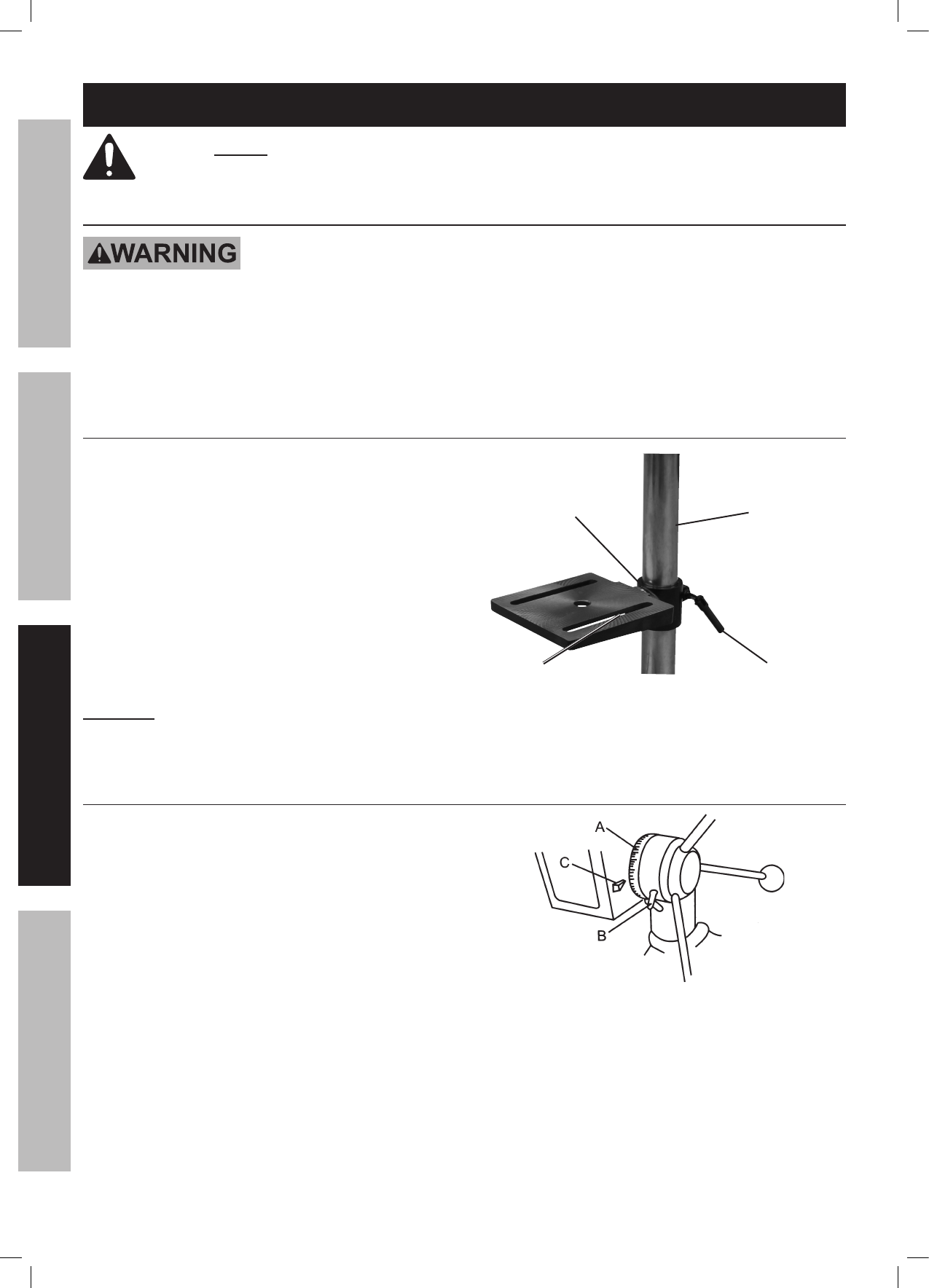
Table Adjustment
1. Adjust the Table (54) by loosening the
Pivot Lever (51), moving the Table,
and tightening the Pivot Lever.
2. Tilt the Table by loosening the Angle Bolt (56) and
tilting to the required angle.
The angle can be read using the Angle Scale (53).
3. TO ENSURE THAT THE DRILL IS ENTIRELY
PERPENDICULAR TO THE TABLE,
insert a straight round bar (not included)
in the Chuck (72), place a square on the
Table (54) and bring it up to the round bar.
Adjust the angle as needed.
CAUTION! To prevent injury from unexpected
Table movement, tighten Angle Bolt (56)
and Pivot Lever (51) after adjustment.
Column (8)
Table
Support (52)
Pivot
Lever (51)
Angle Bolt (56)
under Table
Figure D: Table Adjustment
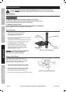
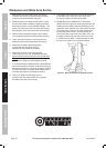
Setting a Drilling Depth
Located around the Spindle Feed Shaft is a
Depth Stop Collar (A) with a scale. The collar is
capable of turning about the shaft, and may be
locked in place by a Locking Screw (B).
1. Lower the drill (with the power OFF) so that it
contacts the material and hold in that position.
2. Loosen the locking screw and turn the collar
so that the measurement for the depth of the
hole required is in line with the pointer (C).
3. Lock the collar in this position using the locking screw.
Figure E: Drill Depth Adjustment
SAFETY OPERATION MAINTENANCESETUP