


SKU 66630 For technical questions, please call 1-800-444-3353. Page 12
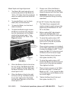
Blade Depth and Angle Adjustment
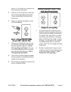
The Blade (96) depth should be set 1.
so that outer points of the Blade are
1/8” to 1/4” higher than the workpiece
while the lowest points are below the
workpiece.
To raise the Blade, turn the Hand-2.
wheel (29) counterclockwise.
To lower the Blade, turn the Hand-3.
wheel clockwise.
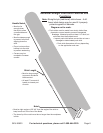
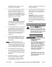
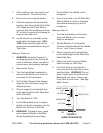
To adjust the Blade’s angle, loosen 4.
the Bevel Lock Knob (62) and then
turn the Handwheel until the Blade
reaches the desired angle. Then
tighten the Bevel Lock Knob. See
Figure A, below.
When the Blade is tilted to the left as 5.
far as it will go, the Blade should be
at a 45° angle to the Saw Table and
the Bevel Indicator on the Ruler (13)
should point to 45°.
When the Blade is tilted to the right 6.
as far as it will go, the Blade should
be at a 90° angle to the Saw Table
and the Bevel Indicator on the Ruler
should point to 0°.
Please note: When the Blade is 7.
at 90° to the Table Saw, the Blade
should be square with the Saw Table.
WARNING! 8. The Bevel Lock Knob
must be tightened during all cutting
operations.
45° and 90° Positive Stop Adjustment
The Table Saw is equipped with 1.
positive stops for rapid and accurate
positioning of the Blade at 45° and
90° to the table.
Before making ANY adjustments, 2.
make sure the Table Saw is un-
plugged and the Switch is removed.
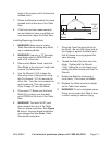
To adjust the positive stop at 90°, 3.
loosen the Bevel Lock Knob and
move as far to the left as possible.
Then tighten the Knob.
Place a level or square (not included) 4.
on the Table (109) with one end blade
to make sure Blade is at 90°. If not,
loosen the Bolt (110) a few turns and
tilt Blade until at the correct angle.
Tighten the Bevel Lock Knob and 5.
then tighten the Bolt (110).
To adjust the positive stop at 45°, 6.
loosen the Bevel Lock Knob and and
move as far to the right as possible.
Then tighten the Knob.
Place a level or square on the Table 7.
with one end blade to make sure
Blade is at 45°. If not, loosen the Bolt
(111) a few turns and tilt Blade until at
the correct angle.
Tighten the Bevel Lock Knob and 8.
then tighten the Bolt (111).
FIGURE A
Handwheel
(29)
Switch (17)
Bevel Lock
Knob (62)