


Page 4 For technical questions, please call 1-800-444-3353. Item 69234
Functional Description
Specifications
Hose Length 25'
Maximum Air Pressure 250 PSI
Air Inlet 1/4″ -18 NPT
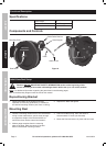
Components and Controls
Hose
Hose Stopper
Guide Roller Bracket
Inlet from
Compressor
Support Post
Outlet to tool
Mounting Plate
Reel Drum
Figure A
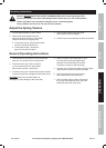
Initial Hose Reel Setup
Read the ENTIRE IMPORTANT SAFETY INFORMATION section at the beginning of this
manual including all text under subheadings therein before set up or use of this product.
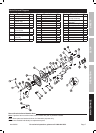
Note: For additional information regarding the parts listed in the following pages,
refer to the Assembly Diagram near the end of this manual.
Repositioning Bracket
1. Remove the Bolts on the Support Post and
reposition to move the guide rollers, if needed, for
the desired mounting location (wall, floor or ceiling).
2. Replace the Bolts and tighten.
Mounting Reel
1. Choose a mounting location that is free of electrical
wiring or other obstructions, and is sturdy enough
to support the weight of the Reel and hose as
well as the force used to extend and retract it.
2. Make a paper template from the mounting
plate of the Reel. Mark the center of the bolt
holes in the desired mounting location.
3. Check for hidden wiring, then, drill holes to
accommodate 1/2" bolts (not included).
4. Mount the Reel and secure in place with four bolts.
SAFETY OPERATION MAINTENANCESETUP