


SKU 90003 PAGE 10
SYMBOLOGY
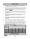
Double Insulated
Canadian Standards
Association
Underwriters
Laboratories, Inc.
Volts Alternating Current
Amperes
No Load Revolutions
per Minute (RPM)
n
o
xxxx/min.
A
V ~
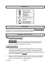
UNPACKING
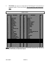
When unpacking, check to make sure all the parts shown on the Parts List on page 15
are included. If any parts are missing or broken, please call Harbor Freight Tools at the
number shown on the cover of this manual as soon as possible.
ASSEMBLY INSTRUCTIONS
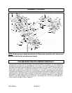
NOTE: For additional information regarding the parts listed in the following pages, refer
to the Assembly Diagram on page 16.
1. WARNING! Always make sure the Power Plug (part #10) of the Bench
Grinder is unplugged from its electrical outlet prior to assembly, adding any
accessories, or making any adjustments to the tool.
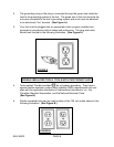
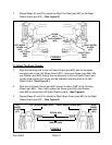
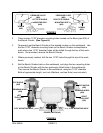
To Attach The Tool Rests:
1. Align the mounting slot in the Left Tool Rest (part #28) with the two threaded
mounting holes in the Left Wheel Guard (part #27). Insert two Screws with two
Lock Washers (part #25) through the mounting slot in the Left Tool Rest, and
loosely finger tighten the two Screws into the threaded mounting holes in the Left
Wheel Guard. (See Figure D, next page.)
2. Slide the Left Tool Rest (part #28) forward to within 1/16” of the Grinding Wheel
(part #64). Then, firmly tighten the two Screws with Lockwashers (part #25) to
secure the Left Tool Rest in place. (See Figure D.)