


SKU 90003 PAGE 13
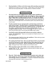
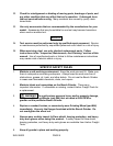
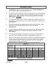
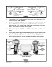
LEFT EYE SHIELD
MOUNTING ROD
(#49)
RIGHT EYE SHIELD
MOUNTING ROD
(#33)
SCREW
(#55)
SCREW
(#55)
PRESSURE PLATE
(#50)
PRESSURE PLATE
(#50)
FIGURE G
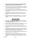
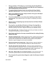
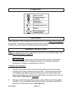
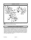
2. There are two 11/32” diameter mounting holes located on the Base (part #15) of
the Bench Grinder. (See Figure H.)
3. Temporarily set the Bench Grinder in the desired location on the workbench. Use
the two 11/32” diameter mounting holes on the Bench Grinder as templates to
mark where two 11/32” diameter holes will be drilled through the top of the work-
bench. Once marked, remove the Bench Grinder.
4. Where previously marked, drill the two 11/32” holes through the top of the work-
bench.
5. Set the Bench Grinder back on the workbench, and align the two mounting holes
on the Bench Grinder with the two previously drilled holes in the workbench.
Then secure the Bench Grinder to the workbench, using two 11/32” diameter
Bolts of appropriate length, two Lock Washers, and two Nuts (none included).
11/32” MOUNTING HOLE
11/32” MOUNTING HOLE
POWER SWITCH (#3)
RIGHT
TOOL REST
(#32)
LEFT
TOOL REST
(#28)
EYE SHIELD
(#26)
EYE SHIELD
(#26)
FIGURE H
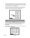
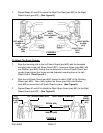
GRINDING WHEEL
(#64)
GRINDING WHEEL
(#64)
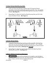
EYE SHIELD (#26) EYE SHIELD (#26)