


SKU 91174 Page 4
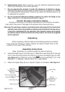
4. Fit the Wheel (8) on the outside of the Left Leg (7) inside the bracket. Position
the Bolt (12) through the bracket on Leg (7), the Wheel (8), and the other side
of the bracket. Tighten with the Nylon Nut (18) on the inside of the Work Stand.
Repeat on the other side of the Leg (7).
See Figure B.
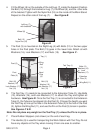
5. The Post (3) is mounted on the Right Leg (4) with Bolts (12) in the two upper
holes in the Post plate. The Bolt (13) goes in the lower hole. Attach all with
Washers (16), Lock Washers (17) and Nuts (15).
See Figure C .
Figure B
Left Leg (7)
with brackets
Wheel (8)
Bolt (12)
Nylon Nut (18)
6. The Tool Tray (1) needs to be connected to the Extension Tube (2). Use Bolts
(10), Washers (16), and Lock Washers (17) to attach the Tray and tighten all
hardware.
See Figure D.
Once the Tool Tray (1) is connected to the Extension
Tube (2), the Tube can be slipped into the Post (3). Choose the height you want
the Tool Tray at, line up the hole in the Extension Tube (2) to the hole in the Post
(3), tighten the Wing Nut (11), and use the Pin on the Post (3) to lock in position.
See Figures C & D.
Note: Do not place any weight on the Tool Tray (1) unless the Pin is in place.
7. Place Rubber Stoppers (not shown) on the end of each leg.
8. The Handle (9) is used for transporting the Work Station with Tool Tray. Do not
have any objects on the Tray when moving it from one area to another.
Post (3)
Post
Plate (3)
Bolt (12)
Washer (16)
Lock Washer (17)
Nut (15)
Hand
Grip
(9)
Tray (1)
Bolt (13)
Washer (16)
Lock Washer (17)
Nut (15)
Wing
Bolt
(11)
Figure C
Figure D
Tool Tray (1)
Wing Bolt (11)
Extention
Tube (2)
Bolts (10,
Washers (16)
Lock
Washers (17)
Pin