


SKU 91176 PAGE 12
ASSEMBLY AND OPERATING INSTRUCTIONS (Continued)
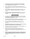
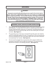
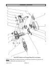
3. Set the speed by adjusting the Variable Speed Switch (5) to either 1 (low) or 2 (high).
High speed is generally used for drilling applications and low speed is generally used
for screw driving applications. See FIGURE 5.
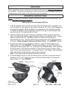
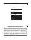
4. Set the Torque by aligning the desired Torque
setting with the Torque Indicator Arrow. See
FIGURE 5. There are seven Torque setting
icons. They range from low driving settings,
to drill settings, to the impact or hammer drill
setting. When using the Hammer Drill set-
ting, line up the Hammer Icon with the Torque
Indicator Arrow as shown in FIGURE 5.
When using the Hammer Drill as a driver, use
the Driver Icons, also shown. The Drill Icon
is not shown in figure 5 but looks like a drill
bit. Higher torque settings (Drill Icon or Ham-
mer) will break the heads off of screws. Only
use the Drill setting to bore or drill into an
object. The Hammer Setting works well when
drilling/chipping into concrete. It is generally
used to bore holes with the purpose of break-
ing up material.
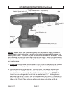
5. Attach a Battery Pack (14) as explained on
page 10.
6. Holding the Hammer Drill clear of all ob-
stacles, test it by gently pulling on the Trig-
ger (16). If the bit turns clockwise, you are in
the drilling or driving position. If the bit turns
counterclockwise, you are in the reverse po-
sition (to remove a screw or help pull a bit
out of a workpiece). Adjust the Reverse
Switch (6) to change direction. Do not use
the Reverse Switch (6) when the drill is rotating.
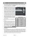
Drilling Tips
7. After the workpiece is secure, use an awl (not included) to punch a starter hole for the
drill bit. Place the bit on the workpiece prior to starting the Hammer Drill. Holding the
Hammer Drill with both hands, gently squeeze the Trigger (16) increasing your tension
on the Trigger (16) after you are sure the bit is securely in the pilot hole. After complet-
ing the task, stop the Hammer Drill, reverse the direction of the drill (see number 6
above), and gently squeeze the Trigger (6) as you back out the drill.
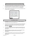
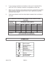
sgnitteSeuqroT
gnitteS
etamixorppAtnuomAeuqroT
)sdnuop-hcnini(
1 3.5-4.4
2 1.7-3.5
3 6.01-1.7
4 7.71-6.01
5 6.62-7.71
6 1.35-6.62
7 7.07
FIGURE 5
Variable Speed Switch (5)
Hammer Icon
Driver Icons
Torque Indicator Arrow