


Page 4
SKU 94847
For technical questions, please call 1-800-444-3353
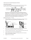
Unpacking
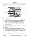
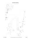
When unpacking, check to make sure the following parts are included. Refer to the Parts
List and Assembly Drawing located at the end of this manual. If any parts are missing or
broken, please call Harbor Freight Tools at the number on the cover of this manual as soon
as possible.
Air Hammer (10)
Hammer Head (3)
Air Hose (12)
Range Adjust Block (6)
Switch Assembly (13)
Regulator (11)
Anvil (5)
Adjustable Pole (7)
Stopper Pin (9)
Mounting Holes (Qty. 4)
Screw (2)
Installation
Mounting “C” Frame
1. Select a workbench in the shop area able to support the weight of the Planishing
Hammer, the metal being worked on, and the vibration of the planishing process.
2. Mount the “C” Frame (1) to the workbench using hardware (not supplied).
The “C” Frame should be positioned so that the mounted Air Hammer (10) is
extended slightly over the edge of the workbench. This will accommodate various
shapes of metals being planished. Hardware should consist of nuts, bolts, at
washers, and lock washers.
Note: There is an entry hole on the side of “C” Frame (1) where sand can be inserted to
reduce noise and vibration.
Air Connection
1. Attach a Union tting (not supplied) into the Switch Assembly Inlet (13) tting.
A Union tting is necessary before a connection can be made to an Air Compressor.
2. For easy connection or removal, attach an Air Coupler (not supplied) to the Union
tting, if quick-coupling is desired.
3. Retighten all couplings and ttings.
4. Attach the Air Hose (not supplied) from the Air Compressor (not supplied) to the
Switch Assembly (13). Place Switch Assy on the oor next to the Planishing Hammer.