


Page 13SKU 95499
For technical questions, please call 1-800-444-3353.
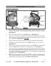
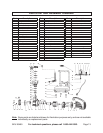
Note: Some parts are listed and shown for illustration purposes only, and are not available
individually as replacement parts.
PARTS LIST AND ASSEMBLY DIAGRAM
24
23
22
21
20
19
18
17
16
15 14 13 12 11
10
9 8
7
6 5 4 3 2
1
25
26
27
28
29
30
31
32
33
34
35
36
37
38
39
40
41
42
43
44 45 46
47
48
49
50
51
52
53
54
55
56
57
58
59
60
61 62 63 64 65 66 67
Part Description
1 Plastic Cowling
2 Spring Washer
3 Washer (#5)
4 Pan Head Screw (M5 x 14)
5 Turbo Fan
6 Screw (M5 x 15)
7 Motor Rear Cover
8 Wave Washer
9 Bearing (6202)
10 Stator Assy.
11 Rotor Assy.
12 Capacitor 150uf/250V
13 Bearing (6204)
14 Oil Seal
15 Nut (M8)
16 Crankcase
17 Crank
18 Screw (M8 x 16 – Left Hand)
19 Crankcase Gasket
20 Crankcase Cover
21 Oil Sight Glass
22 Hex Head Screw
23 Pan Head Screw (M6 x 14)
Part Description
24 Oil Breather Cap
25 Spring Washer (#8)
26 Washer (#8)
27 Screw (M8 x 20)
28 Connecting Rod
29 Piston
30 Circlip (#12)
31 Piston Pin
32 Cylinder Gasket
33 Cylinder
34 Spring Washer (#6)
35 Washer (#6)
36 Screw (M6 x 40)
37 Oil Clean Ring
38 Seal Ring
39 Valve Plate Gasket
40 Valve Plate Assy.
41 Air Intake Valve
42 Limit Pin
43 Cylinder Head Gasket
44 Air Filter Element Assy.
45 Cylinder Head
46 Square Elbow Connector
Part Description
47 Exhaust Pipe Assy.
48 Non-Return Valve Assy.
49 Unload Pipe Assy.
50 Tank
51 Nut (M6)
52 Rubber Foot
53 Screw (M6 x 20)
54 Tank Drain Valve
55 Power Cord
56 Rear Motor Cover Gasket
57 Seal Washer
58 Connector Seat
59 Connector
60 Wheel Sleeve
61 Safety Release Valve
62 Tank Pressure Gauge
63 Pressure Switch
64 Connector
65 Tool Pressure Gauge
66 Regulator
67 Air Outlet Valve