


Page 5SKU 97385 For technical questions, please call 1-800-444-3353.
Insert the Vacuum attachment (12) 2.
onto the center Screws. Attach one
Washer (15) onto each Screw. Attach
the Slide Knobs (10) to the Screws
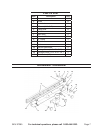
and tighten. (See Assy. Diagram.)
Insert the Extension Rods (2) into the 3.
outer channels of the Fence Slide (5)
at the Fence (1) side.
(See Assy. Diagram.)
Slide the head of the Carriage 4.
Screws (14) into the center channel
of the End Slide (6).
(See Assy. Diagram.)
Attach the Block Stop (7) to the 5.
protruding Carriage Screw (14) while
aligning the tangs on the Block Stop
with the center channel face of the
Fence Slide (5). Attach a Flat Wash-
er (15) and Knob (11) to the Screw
and tighten.
NOTE: The Block Stop slides
through the entire length of the Fence
Slide. Use the Block Stop for repeti-
tive work. If not needed, loosen the
securing Knob (11) and slide the as-
sembly off the Fence Guide (2).
(See Assy. Diagram.)
Attach the “C” Clamp (9) onto the 6.
Carriage Screws (14), noting that
one end is locked into the slot in the
Fence (1) and the other end rests
on the Extension Rod (8). Attach
a Washer (15) and Knob (11) and
tighten. (See Assy. Diagram.)
Position a Guide (2) under the Fence 7.
(1). Insert T-Screw (4) from under-
neath through Guide (2), Fence (1)
(3) onto T-Screw (4) and tighten
clockwise. Attach the other Guide
using the same procedure. To at-
tach and secure the Router Table
Fence on a Router Bed, slide the two
Guides (2) onto the rails on the Rout-
er Bed. (See Assy. Diagram.)
OPERATING INSTRUCTIONS
Read the ENTIRE IMPORTANT
SAFETY INFORMATION section
at the beginning of this manual
including all text under
subheadings therein before set
up or use of this product.
Tool Set Up
TO PREVENT
SERIOUS INJURY
FROM ACCIDENTAL
OPERATION: Make sure the
power switch of the router or
drill press is in its “OFF”
position and the machine is
unplugged from its electrical
outlet before performing any
set up procedures.
After the Router Table Fence is 1.
mounted to the router/drill press table
top, adjust the Router Table Fence by
loosening the two Adjusting Screws
(3). (See Assy. Diagram.)
Slide the Router Table Fence forward 2.
or backward to where you need to
stop your material. Then tighten the
two Adjusting Screws (3) to secure
the Router Table Fence in place.
Always tighten both Adjusting Screws
to ensure a secure connection.
(See Assy. Diagram.)
An additional adjustment may be 3.
made to where you need to stop your
WARNING