


Page 4SKU 98085 For technical questions, please call 1-800-444-3353.
SPECIFICATIONS
Charge Time 6-8 hours
Power Source
(5), 1.2V, 600 mAh/6V, Ni-Cd
rechargeable battery pack
Range
Detects motion over a range of
120° at 16 feet.
Delay 5-60 seconds
Working
Conditions
14° - 131° F
<80% RH
UNPACKING
When unpacking, check to make sure
that the item is intact and undamaged. If
any parts are missing or broken, please
call Harbor Freight Tools at the number
shown on the cover of this manual as soon
as possible.
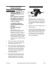
ASSEMBLY
Read the ENTIRE IMPORTANT
SAFEGUARDS section at the
beginning of this manual
including all text under
subheadings therein before set
up or use of this product.
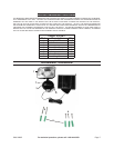
Note: For additional information 1.
regarding the parts listed in the fol-
lowing pages, refer to the Assembly
Diagram near the end of this manual.
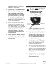
The Security Light should be set up 2.
at a location where you desire to
have extra lighting to detect persons
or objects moving at night or in the
dark.
Decide where you want to place the 3.
Lamp (1) and Solar Panel (2). The
Light is equipped with a connect-
ing wire, so the Lamp (1) and Solar
Panel (2) can be installed only as far
apart as the connecting wire allows.
Choose a location that receives full, 4.
direct sunlight a minimum of eight
hours a day. The location should not
be near nighttime light sources such
as porch lights or streetlights as this
will cause the Light to remain off.
During the day, the Solar Panel con-5.
verts sunlight into electricity which
recharges the batteries. The amount
of light the Solar Panel receives
depends on placement of the Light,
geographic location and weather. If
the weather is cloudy and the panel
did not receive a full charge, the Light
may not achieve full operating time.
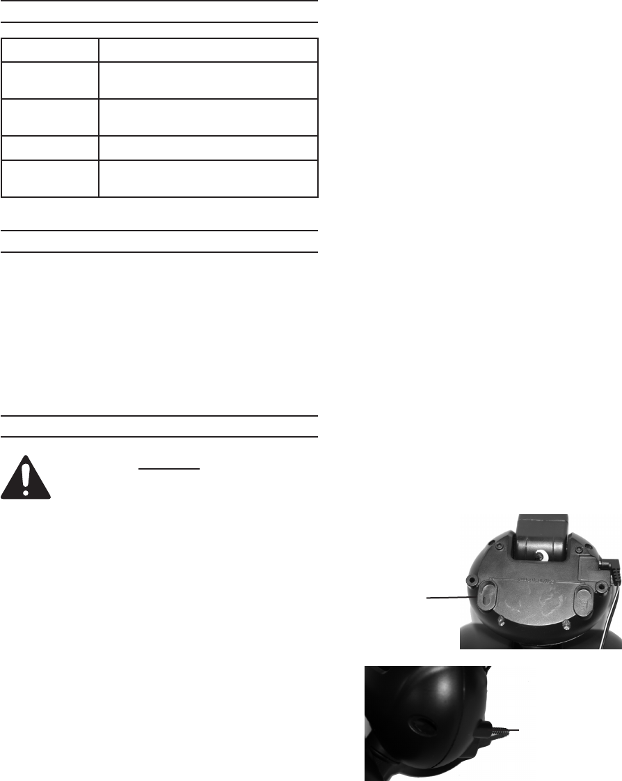
Mount the Lamp (1) on a solid sur-6.
face capable of supporting the Lamp
(1) and secure enough so that it will
not move when exposed to vibration
or wind.
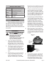
rear-
mounting
holes
inside-
mounting
holes
Figure 1
7. To mount the Lamp (1), the Screws
(5) can be inserted into either the
rear mounting holes or to the inside
mounting holes as shown in Fig. 1.
If using the inside mounting holes,