


10
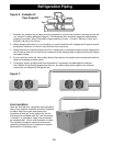
Refrigeration Piping
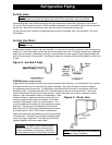
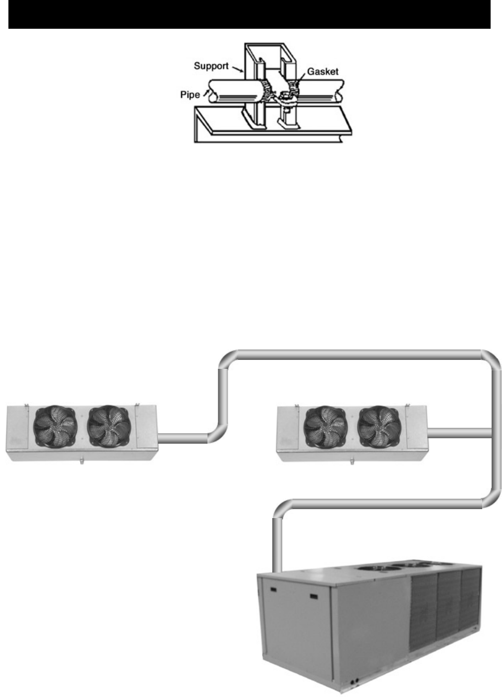
1. Normally, any straight run of tubing must be supported in at least two locations near each end of the
run. Long runs require additional supports. The refrigerant lines should be supported and fastened
properly. As a guide, 3/8 to 7/8 should be supported every 5 feet, 1-1/8 and 1-3/8 every 7 feet; and 1-
5/8 and 2-1/8 every 9 to 10 feet.
2. When changing directions in a run of tubing, no corner should be left unsupported. Supports should
be placed a maximum of 2 feet in each direction from the corner.
3. Piping attached to a vibrating object (such as a compressor or compressor base) must be supported in
such a manner that will not restrict the movement of the vibrating object. Rigid mounting will fatigue
the copper tubing.
4. Do not use short radius ells. Short radius elbows have points of excessive stress concentration and are
subject to breakage at these points.
5. Thoroughly inspect all piping after the equipment is in operation and add supports wherever
line vibration is significantly greater than most of the other piping. Extra supports are relatively
inexpensive as compared to refrigerant loss.
Line Insulation
After the final leak test, refrigerant lines exposed to
high or low ambient conditions should be insulated
to reduce heat loss or gain and prevent the
formation of flash gas in the liquid lines. Suction
lines should be insulated with 3/4" wall Armstrong
“Armaflex” or equivalent. Liquid lines should also
be insulated with 1/2-inch wall insulation or better.
The insulation located in outdoor environments
should be protected from UV exposure to prevent
deterioration of insulating value.
Figure 6. Example of
Pipe Support
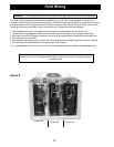
Figure 7.