


H.E.R.O. INDUSTRIES LTD. 1000MD OWNERS MANUAL - “B” VERSION
16
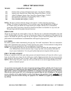
TROUBLESHOOTING
SITUATION
POSSIBLE CAUSE (REMEDY)
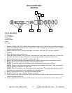
ELECTRIC MOTOR WON'T START/RUN
1. Unit unplugged or building circuit fuse is blown. (check, replace or reset fuse)
2. Pump under pressure. (reduce pressure setting by turning pressure control knob counter-clockwise,
trigger gun to relieve pressure).
3. Too light or too long of extension cord. (replace with correct cord. If distance greater than 100 feet,
obtain and install extra length of H.E.R.O. airless spray hose).
4. Unit's thermal overload switch has opened. (determine and correct cause of overheating).
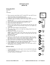
ELECTRIC MOTOR STALLS/QUITS
1. See "Electric Motor Won't Start/Run
2. Drive belt is loose. (tighten drive belts by evenly turning belt tension bolts on either side of motor
clockwise. Loose belts generally emit loud squealing noises).
3. Unit builds pressure, but pump “seizes” or “stops” when gun is triggered. ( loose belts, tighten).
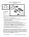
NO PRESSURE, BLUE HYDRAULIC FLUID IN PAINT
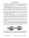
1. Hydrapulse membrane broken. (replace hydrapulse membrane,(ref# 46). Closely follow detailed
instructions on page 20. NOTE; If, and only if, paint has contaminated the hydraulic side of the pump,
the entire hydraulic system must be cleaned and flushed. Make sure to remove and clean the hydraulic
tank screen,(ref# 63), during this process. Refill only with genuine H.E.R.O. LVO hydraulic fluid.
NOTE; If lacquer has contaminated the hydraulic system, the piston seal, (ref# 87), must be changed in
addition to flushing the system. Closely follow detailed instructions on page 23-24).
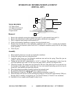
HYDRAULIC SIDE OF PUMP HAS BEEN REPAIRED AND REASSEMBLED, HYDRAPULSE
MEMBRANE NOT MOVING "PURGING"
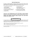
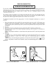
1. Air lock created on hydraulic side of pump. (when the hydraulic side of the pump is working there is no
air in it. During repairs it is possible that air has been trapped in the hydraulic system. It must be
removed or the pump will not work. To purge the air from the hydraulic system; remove the pressure
control knob,(ref# 71), from the valve. Gently pull the P.C. stem,(ref# 74), out. It will pull out about
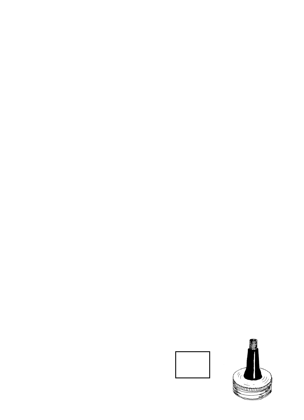
1/8". Remove the vented hydraulic cap,(ref# 65), from the hydraulic tank,(ref# 62), and install accessory
pressure cap, item 4-45-3. With a bicycle pump, apply a few pounds of air pressure to the hydraulic tank.
This will force the oil through the hydraulic system and push out any of the trapped air. Wait a few
minutes. Remove pressure cap and replace with vented cap. Restart the unit and install pressure control
knob. NOTE: Unit may be running during purging procedure to speed up the procedure. If a pressure cap
is unavailable, simply running the equipment for approximately 5-10 minutes with the P.C. stem pulled out,
will purge the system).
Accessory
Item
4-45-3