


H.E.R.O. INDUSTRIES LTD. 1000MD OWNERS MANUAL - “B” VERSION
17
TROUBLESHOOTING
SITUATION
POSSIBLE CAUSE (REMEDY)
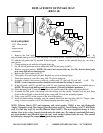
TOTAL LOSS OF PRESSURE, HYDRAPULSE MEMBRANE MOVEMENT CANNOT BE STOPPED
OR ALTERED. (SEE "HYDRAPULSE MEMBRANE TEST")
1. Paint too thick. (thin paint according to manufacturer's recommendations).
2. Intake ball (ref# 20) worn or jammed opened/closed. (remove intake endcap (ref# 16) and ball guide
(ref# 23). Inspect intake ball,(ref# 20), to ensure it is free, round, and has no nicks or cuts. Inspect ball
guide for excessive "bashing out" on the internal walls. Excessive wear causes the ball to become "lost"
and unable to locate the seating surface. Inspect for foreign material jamming ball. Replace parts as
needed).
3. Intake seat loose/bypassing. (remove intake endcap,(ref# 16) and ball guide, (ref# 23). remove seat (ref#
18) and inspect washer (ref# 17) for excessive compression. Inspect for any sign of material bypass
between intake seat and endcap cavity. NOTE; The proper alignment of intake parts, condition of intake
washer, o-rings, combined with the correct bolt torque are critical to the correct function of the intake
valve. Replace the intake washer (ref# 17), each time the endcap is removed.
4. Outgo valve ball (ref# 36) worn or jammed. (remove outgo valve,(ref# 32). Invert valve and unthread
outgo valve upper,(ref# 39), from outgo lower,(ref# 33). Remove crush washer,(ref# 34), outgo seat,
(ref# 35), outgo ball,(ref# 36), outgo cage,(ref# 37), outgo spring,(ref# 38), from outgo upper tunnel.
Inspect outgo ball to ensure that it is round and free of nicks or cuts. Inspect for foreign material
jamming ball. Inspect ball and cage for wear. Replace parts as needed).
5. Outgo valve (ref# 32) incorrectly assembled. (disassemble and reassemble outgo valve, closely
following detailed instructions on page 22).
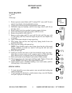
TOTAL LOSS OF PRESSURE, HYDRAPULSE MEMBRANE HAS NO MOVEMENT OR
MOVEMENT CAN BE STOPPED. (SEE "HYDRAPULSE MEMBRANE TEST")
1. Hydraulic intake valve (ref# 59) defective. (remove hydraulic feed line,(ref# 60), from hydraulic
intake valve. Plug hydraulic feed line so hydraulic fluid does not drain. Remove hydraulic intake valve
from elbow,(ref# 147). Check hydraulic intake valve to ensure that it flows in one way only, into the
cylinder. Replace if necessary. NOTE; Item cannot be repaired ).
2. Air lock created on hydraulic side of pump. (air entering hydraulic side due to loose hydraulic feed
line fittings, (ref# 60), punctured hydraulic feed line, poor seal at hydraulic intake valve, (ref# 59), or
elbow, (ref# 147). Tighten hydraulic feed line, test for leaks, or apply Teflon tape or pipe sealant on
fittings. Purge air as per detailed instructions below).
3. Pressure control valve ball (ref# 84) worn out/jammed. (remove hydraulic return line, (ref# 69), from
pressure control valve fitting,(ref# 78). Remove pressure control valve,(ref# 70), from elbow, (ref# 59).
Disassemble pressure control valve, by removing valve seat,(ref# 83), from body, (ref# 79). Inspect for
and remove foreign material. Inspect ball for wear. Install pressure control repair kit,(ref# 85), if
necessary).
4. Piston rod (ref# 90) disconnected from piston (ref# 88). (reconnect piston rod following detailed
instructions on page 23-24).
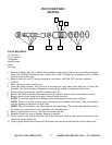
SPRAYER DOES NOT PRIME WITH PAINT
1. Heavy bodied paint, air lock. (refer to " Setting Up To Spray" and follow instructions.