Appendix A
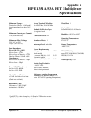
HP E1351A/53A FET Multiplexer
Specifications
* Each FET is diode clamped to ±14V and a 220Ω series resistor.
This limits the current to the clamp diodes.
Maximum Voltage:
Terminal to Chassis: ±16V peak*
(input impedance less above 14V
peak)
Maximum Current per Channel:
1 mA (non-inductive)
Maximum Offset Voltage:
25 µV (0° to 28°C)
250 µV (28° to 55°C)
Input Impedance:
Power On (Vin <±10V)
High to Low: >10
8
Ω
High or Low to Chassis: >10
8
Ω
Guard to Chassis: 10 kΩ ±10%
Capacitance:
High or Low to Chassis: <200pf
High to Low: <200pf
Power Off (High to Low):
for Vin ≤14V: 1000Ω
for Vin >14V: 220Ω
Closed Channel Resistance:
<3.1 kΩ for high or low input
(Guard not switched)
Bandwidth (-3dB):
50Ω source, 1 MΩ | |10pF
termination: >200 kHz
Screw Terminal Wire Size:
16 AWG Max, 26 AWG Min
Module Size/Device Type:
B, register-based
Connectors Used: P1
Number of Slots: 1
Interrupt Level: selectable
Power Requirements:
Voltage: +5V +12V
Peak module
current, IPM (A): 0.20 0.13
Dynamic module
current, IDM (A): 0.01 0.01
Strain Gage Excitation:
+ 4.63V ±10%
Max Current: 400mA
(short circuit protected)
Reference Junction Measurement
Accuracy (HP E1353A only): 0.3°C
(over 18° to 28°C operating temperature)
Watts/Slot: 1
Cooling/Slot:
0.02 mm H
2
O @ 0.10 liter/sec
Humidity: 65% 0° to 40°C
Operating Temperature:
0° to 55°C
Storage Temperature:
-40° to 75°C
EMC, RFI, Safety:
meets FTZ 1046/1984, CSA 556B,
IEC 348, UL 1244
Net Weight (kg): 0.9
Appendix A HP E1351A/53A FET Multiplexer Specifications 79


