


©Copyright 2008 Liberty Pumps Inc. All rights reserved - 7 -
2. The control panel is preferably mounted in a cool, dry environment. Installation and connections are specific to
the control panel. Control panels should be installed and serviced only by a qualified electrician (Refer to Figure
2, page 10).
4-3 STEPS TO BE TAKEN BEFORE ENERGIZING
1. Retighten all field-made connections. Retighten all factory-made connections. These may have loosened due to
shipping and handling vibrations.
2. Check the security of mounting hardware.
3. Check the enclosure to see that it has not been damaged in such a manner as to reduce electrical spacing.
4. Rotate the cutter wheel with the hex socket head cap screw to verify movement and lubricate the seals.
5. Ensure that no wires or other obstacles are in the way of the pump cutter.
6. Conduct an electrical insulation resistance test to make sure that the control panel is free from short circuits and
ground faults. This should be done both phase-to-phase and phase-to-ground.
7. MOTOR OVERLOAD PROTECTION: The pump motor is protected from locked rotor and running overloads by a
thermal overload integrally mounted to the motor. No adjustments are required.
Check to determine that all grounding connections are made properly
8. If a panel is used, remove all debris, scrap wire, etc., from the control panel interior before closing the doors.
Install covers, close doors making certain that no wires are pinched and that all enclosure parts are properly
aligned and tightened.
ENERGIZING THE CONTROL PANEL OR BREAKER FOR THE FIRST TIME IS POTENTIALLY
DANGEROUS. LICENSED ELECTRICAL PERSONNEL SHOULD BE PRESENT WHEN THE PANEL
OR BREAKER IS ENERGIZED FOR THE FIRST TIME. IF FAULTS CAUSED BY DAMAGE OR POOR
INSTALLATION PRACTICES HAVE NOT BEEN DETECTED, SERIOUS DAMAGE CAN RESULT
WHEN POWER IS APPLIED (REFER TO SECTION 5).
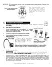
4-4 FLOAT SWITCHES
1. The pump's on and off cycles are normally controlled by a "piggy back" float switch attached to the side of the
pump, or by hanging switches in the wet well. Refer to panel or switch instructions for proper electrical
connection
4-4.1 FLOAT SEQUENCE- PIGGY BACK (AUTOMATIC MODELS LSG202A & LSGX202A)
1. As the liquid level in the wet well rises, the float tilts, closing the switch. This starts the pump.
2. The pump runs until the liquid level falls below the “PUMP OFF” level of the float (Factory set at 7" minimum),
emptying the wet well.
4-4.2 FLOAT SEQUENCE- SIMPLEX (MANUAL MODELS)
1. As the liquid level in the wet well rises, the “PUMP OFF” float tilts, closing the switch (This level must be set at a
minimum of 7"). As the liquid level continues to rise, the “PUMP ON” float tilts. This switch closes, starting the
pump.
2. The pump runs until the liquid level falls below the “PUMP OFF” float, emptying the wet well.
3. In the event of a malfunctioning float switch, control relay or pump, the liquid level rises and tilts the “HIGH LEVEL
ALARM” float. The alarm system will activate.
4-4.3 FLOAT SEQUENCE-DUPLEX (MANUAL MODELS)
1. As the liquid level in the wet well rises, the “PUMP OFF” tilts, closing the switch. As the liquid level continues to
rise, the “LEAD PUMP ON” float tilts. This switch closes, starting the lead pump. The pump runs until the liquid
level falls below the “PUMP OFF” float, emptying the wet well.