


308715 21
Displacement Pump Repair
WARNING
INJECTION HAZARD
To reduce the risk of serious injury,
whenever you are instructed to relieve
pressure, follow the Pressure Relief
Procedure on page 9.
NOTE: Packing Repair Kit 235703 is available. Refer-
ence numbers of parts included in the kit are marked
with an asterisk, i.e., (121*). For the best results, use
all the new parts in the kit, even if the old ones still look
good.
NOTE: To minimize down time, and for the best sprayer
performance, check the motor brushes (see page 19)
and clean the transducer (see page 27) whenever you
repack the pump. Replace these parts as needed.
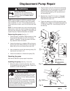
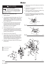
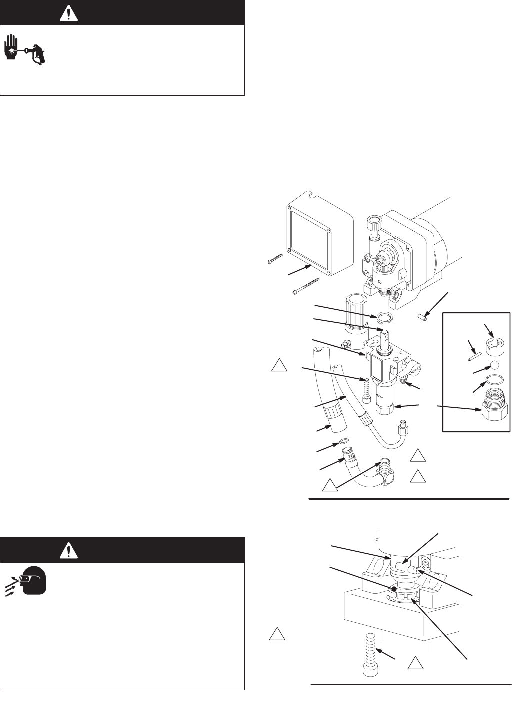
Removing the pump (See Fig. 17.)
1. Flush the pump, if possible. Relieve pressure. Stop
the pump with the piston rod (107) in its lowest
position, if possible. To lower the piston rod manu-
ally, rotate the motor fan blades.
2. Loosen the swivel nut on adapter (38) and remove
suction hose (32). While pushing in on the collar of
elbow (36), pull out and remove drain tube (33).
3. Use a screwdriver to push the retaining spring (18)
up and push out the pin (17).
4. Loosen the screws (21). Remove the pump (20).
Repairing the pump
See manual 308190 for pump repair instructions.
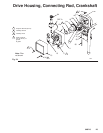
Installing the pump (See Fig. 18 and 19.)
1. Mount the pump on the drive housing. Tap it into
the alignment pins with a soft hammer. Tighten the
screws (21) to 50 ft-lb (68 N.m).
WARNING
MOVING PARTS HAZARD
Be sure the retaining spring (18) is firmly
in the groove all the way around, to pre-
vent the pin (17) from working loose due
to vibration.
See Fig. 18.
If the pin works loose, it or other parts could break
off due to the force of the pump action. These parts
could be projected into the air and result in serious
injury or property damage, including the pump
connecting rod or drive housing.
2. Align the hole in the rod (107) with the connecting
rod assembly (15). Use a screwdriver to push the
retaining spring (18) up and push in the pin (17).
Push the retaining spring (18) into place around
the connecting rod.
3. Replace the o-ring (27) if it is worn or damaged.
Reconnect the suction and drain hoses (32,33).
Install the front cover (13).
4. Tighten the packing nut (102) just enough to stop
leakage, but no tighter. Fill the packing nut/wet-cup
1/3 full with Graco TSL. Push the plug (123) into
the wet-cup.
02832B
Fig. 17
1
2
Torque to
50 ft–lb (68 N.m)
118
*119
*121
*122
120
17
18
20
2
33
32
38
21
1
13
107
36
Apply anaerobic
polyacrylate pipe
sealant
27
Fig. 18
17
18
123
15
102
1
Torque to
50 ft–lb (68 N.m)
1
04655
21