


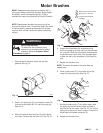
308715 27
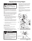
Pressure Transducer
WARNING
INJECTION HAZARD
To reduce the risk of serious injury,
whenever you are instructed to relieve
pressure, follow the Pressure Relief
Procedure on page 9.
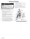
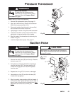
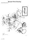
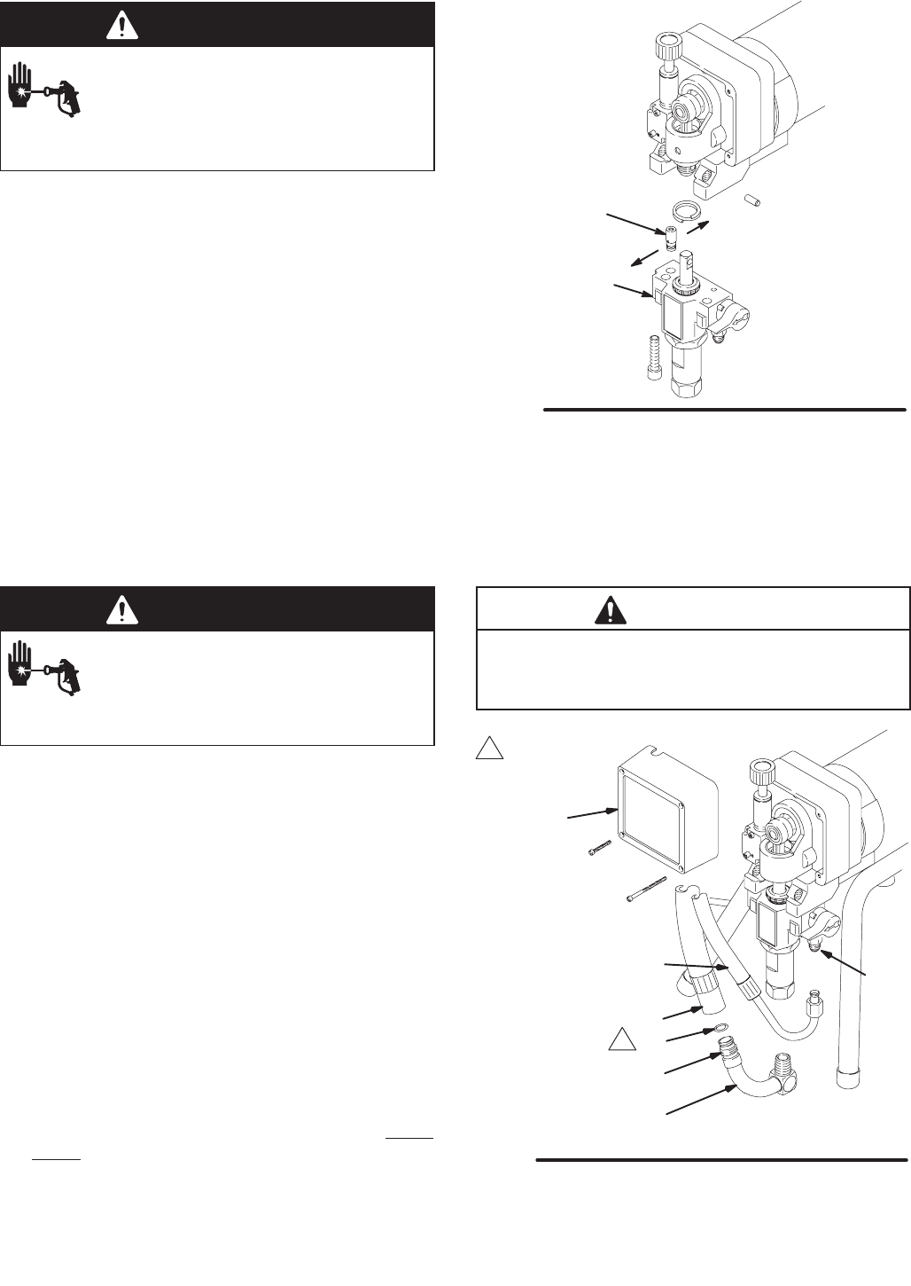
NOTE: See Fig. 26 for this procedure.
1. Remove the displacement pump. See page 21.
2. Use a pull–twist motion to remove the transducer
(29) from the pump manifold (101).
3. Clean paint residue from the hole in the manifold;
do not scratch the surface of the hole.
4. Lightly apply oil to the o-ring of the new transducer.
5. Install the transducer in the pump manifold, while
guiding the o-ring and backup ring into place.
6. Align the holes in the transducer as shown by the
arrows in Fig. 26.
7. Install the displacement pump. See page 21.
Fig. 26
02817A
101
29
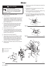
Suction Hose
WARNING
INJECTION HAZARD
To reduce the risk of serious injury,
whenever you are instructed to relieve
pressure, follow the Pressure Relief
Procedure on page 9.
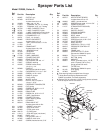
1. Remove the drain hose (33) from the clip. Remove
the front cover (13).
2. Pull upward on the hose (32) while unscrewing it
from the inlet tube (38). The hose coupling (A)
threads will engage and the hose will separate
from the tube.
3. Replace the o–ring (27) if it is worn or damaged.
4. Lubricate the o–ring (27) and the inlet tube (38)
threads with light grease.
5. Align the suction hose coupling with the threads of
the inlet tube (38). Tighten the hose onto the tube at
least 4 turns to ensure that the threads have disen-
gaged and can function as a swivel joint.
CAUTION
Misalignment or cross-threading will damage the
parts and/or create shavings which can cause the
o–ring (27) to leak.
06978
33
32
36
38
27
13
A
Fig. 27
1
Lubricate
1
Note: Filter
not shown