


16 308640
Service
WARNING
INJECTION HAZARD
To reduce the risk of a fluid injection
injury, follow the Pressure Relief Proce-
dure on page 7 before checking or
servicing any of the system equipment and when-
ever you are instructed to relieve pressure.
NOTE:
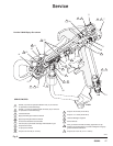
D Follow the Service Notes in Fig. 8 when reassem-
bling the gun. Refer to the parts drawing for your
gun model (page 18 or 20) for parts not shown in
Fig. 8.
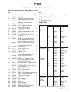
D Repair Kits are available. See page 19 or 21 for the
kits for your gun model.
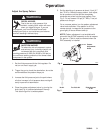
Air Valve Service
1. Relieve the pressure as instructed on page 7.
2. Remove the trigger (3) and valve cap (7). See the
parts drawing and Fig. 8.
3. Unscrew the needle nut (23) while holding the flats
(C) of the air valve (26) stem with a long nose
pliers.
CAUTION
To avoid leakage, be careful not to scratch the air
valve stem.
4. Remove the spring (6) and air valve (26).
5. If there is air leakage at the air valve (26), unscrew
the packing nut (24) and carefully remove the
u-cup packing (25). Replace packing if worn or
damaged. When re-installing, be sure the u-cup
faces inward.
6. If leakage occurs internally or the front of the gun
leaks air when it’s not triggered, clean and inspect
the air valve and the spring for wear or damage.
Replace as needed.
7. For best air valve life, lubricate the external air
valve stem (C) with light oil after each day’s use.
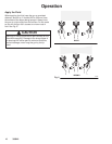
Fluid Needle Cartridge Service
Follow the procedure below to remove the fluid needle
cartridge for cleaning or for replacement.
1. Relieve the pressure as instructed on page 7.
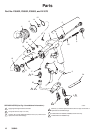
2. Remove the tip guard or AA RAC assembly (11),
air cap or RAC housing (13), spray tip (14), and air
separator (16 –
part no. 238402, 238852, 238883,
and 241070 guns only
). See Fig. 8.
3. Trigger the gun to back the fluid needle ball off the
seat. Remove the diffuser-seat (15).
4. Remove the trigger (3) and trigger extension
pieces (19). See the Parts Drawing, page 18.
5. To remove the fluid needle cartridge (10), slide the
notch of the packing tool (34) around the small
diameter of the trigger guide (A) and pull the
cartridge toward the front of the gun.
6. Remove the fluid gasket (18).
7. If the fluid needle cartridge was removed for
cleaning, remove the external o-ring (10a) and
backup ring (10b). Clean the needle cartridge
thoroughly with a compatible solvent and a soft
brush. Install a new o-ring (10a) and backup ring
(10b).
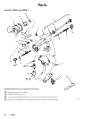
8. Lubricate the o-ring (10a) and backup ring (10b) of
the new or cleaned needle cartridge with light-
weight oil.
9. Insert the fluid needle cartridge into the front end
of the gun body. Use the packing tool (34) to pull
back on the cartridge until it snaps into place; the
cartridge must be bottomed out in the gun body
insert. If the cartridge is seated properly, the
needle cartridge washer (B) will be visibly seated
flat through the back end of the gun body insert.
10. Insert a new gasket (18).
11. Install the gun trigger and trigger extension pieces.
12. Lubricate the diffuser-seat (15) thread. Trigger the
gun while screwing the diffuser-seat back into the
gun. Torque the diffuser-seat to 90 to 100 in-lb
(10.2 to 11.2 NSm).
13. Install the gun air separator
(part no. 238402,
238852, 238883, and 241070 guns only)
, spray tip,
air cap or RAC housing, and tip guard or AA RAC
assembly.