


309067 5
Basic Problem Solving
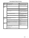
TYPE OF
PROBLEM
WHAT TO CHECK
If check is OK, go to next check
WHAT TO DO
When check is not OK, refer to this column
Electrical
(continued)
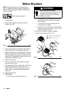
4. Motor brushes for the following:
a. Loose terminal screws.
b. Broken or misaligned brush springs.
c. Brushes binding in holders.
d. Broken leads.
e. Worn brushes.
f. Brush leads snagged on spring clip.
NOTE: Brushes do not wear at same rate on both
sides of motor. Check both brushes.
4. Refer to page 10.
a. Tighten.
b. Replace broken spring and/or align
spring with brush
c. Clean brush holders. Remove carbon
with small cleaning brush. Align brush
leads with slot in brush holder to as-
sure free vertical brush movement.
d. Replace brushes
e. Replace brushes if less than 0.5 in.
(12.5 mm) long.
f. Correctly route wires. See page 10.
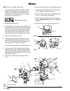
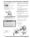
5. Motor armature commutator for burn spots, gouges and
extreme roughness. Remove motor cover and brush in-
spection plates to check. See page 10.
5. Remove motor and have motor shop
resurface commutator if possible.
See page 12.
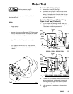
6. Motor armature for shorts using armature tester (growler)
or perform motor test. See page 9.
6. Replace motor. See page 12.
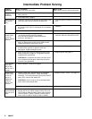
7. That leads from pressure transducer and motor to motor
control board (22a) are securely fastened and properly
mated.
7. Replace loose terminals; crimp to leads.
Be sure male terminal blades are straight
and firmly connected to mating part.
8. Motor control board (22a) by performing motor control
board diagnostics on page 13. If diagnostics indicate, sub-
stitute with a good board.
CAUTION: Do not perform this check until motor armature
is determined to be good. A bad motor armature can burn
out a good board.
8. Replace board. See page 13.
9. Power cord (30).
232918, 232915, 232914, 232665. Disconnect brown and
blue power cord terminals; connect volt meter to these
leads.
Plug in sprayer. Meter must read 210–250 VAC.
232910 – 232913, 232919. Disconnect brown and blue
power cord terminals; connect volt meter to these leads.
Plug in sprayer. Meter must read 105–125 VAC.
232916, 232917.Disconnect black and white power cord
terminals; connect volt meter to these leads.
Plug in sprayer. Meter must read 90–110 VAC.
Unplug sprayer.
9. Replace power cord.
See page 14.
10. ON/OFF switch (80).
232918, 232915, 232914, 232665. Disconnect brown wire
(96) between motor control board (22a) and switch and
connect volt meter between exposed terminal switch and
power cord blue wire (94). Plug in sprayer and turn ON.
Meter must read 210–250 VAC.
232910 – 232913, 232919. Disconnect brown wire (96)
between motor control board (22a) and switch and con-
nect volt meter between exposed terminal switch and
power cord blue wire (94). Plug in sprayer and turn ON.
Meter must read 105–125 VAC.
232916, 232917.Disconnect black wire (96) between
motor control board (22a) and switch and connect volt
meter between exposed terminal of (96) and power cord
white wire. Plug in sprayer and turn ON.
Meter must read 90–110 VAC.
Turn OFF and unplug sprayer.
10. Replace ON/OFF switch. See page 14.