


19
English
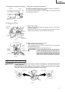
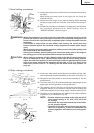
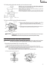
7. Bevel cutting procedures
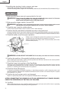
(1) Loosen the clamp lever and bevel the saw blade to the left or to
the right.
When tilting the motor head to the right pull the fixing pin
towards the rear.
(2) Adjust the bevel angle to the desired setting while watching
the bevel angle scale and indicator, then secure the clamp le-
ver.
(3) Follow the procedures indicated in paragraphs 5 and 6 above.
For maximum dimensions for bevel cutting, refer to
“SPECIFICATIONS” table on page 9.
Fig. 24
WARNING: When the workpiece is secured on the left or right side of the blade, the short cut-off
portion will come to rest on the right or left side of the saw blade. Always turn the
power off and let the saw blade stop completely before raising the handle from the
workpiece.
If the handle is raised while the saw blade is still rotating, the cut-off piece may
become jammed against the saw blade causing fragments to scatter about danger-
ously.
When stopping the bevel cutting operation halfway, start cutting after pulling back
the motor head to the initial position.
Starting from halfway, without pulling back, causes the safety cover to be caught in
the cutting groove of the workpiece and to contact the saw blade.
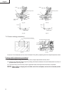
CAUTION: When cutting a workpiece of 2-3/8" (60mm) height in the left 45° bevel cutting posi-
tion or a workpiece of 1-3/8" (35mm) height in the right 45° bevel cutting position,
adjust the lower limit position of the motor head so that the gap between the lower
edge of the motor head and the workpiece will be 5/64" to 1/8" (2 to 3mm) at the
lower limit position (refer to “3. Checking the saw blade lower limit position” on
page 14).
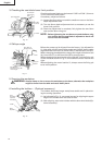
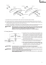
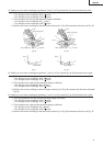
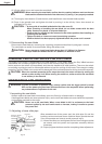
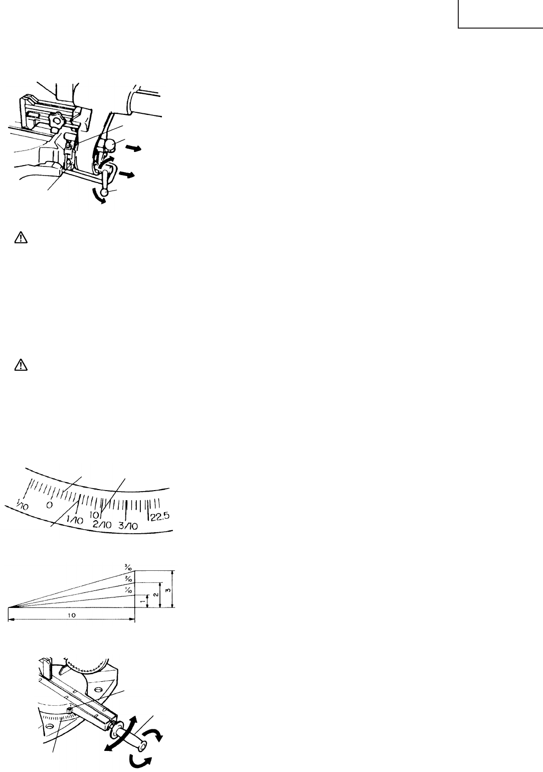
8. Miter cutting procedures
(1) Loosen the side handle and adjust the turntable until the indi-
cator aligns with the desired setting on the miter scale (Fig. 27).
(2) Re-tighten the side handle to secure the turntable in the de-
sired position.
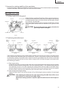
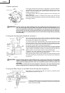
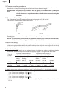
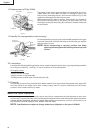
(3) The miter scale (Fig. 25) indicates both the cutting angle on the
angle scale and the gradient on the grade scale.
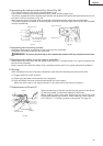
(4) The gradient, which is the ratio of the height to the base of the
triangular section to be removed, may be used for setting the
miter scale instead of the cutting angle, if desired (see Fig. 26).
(5) Therefore, to cut a workpiece at a grade of 2/10, set the indicator
to position a as indicated in Fig. 25.
NOTE: * Positive stops are provided at the right and left of
the 0° center setting, at 15°, 22.5°, 31.6°, 35.3° and
45° settings.
Check that the miter scale and the tip of the indica-
tor are properly aligned.
* Operation of the saw with the miter scale and indi-
cator out of alignment, or with the side handle not
properly tightened, will result in poor cutting preci-
sion.
Indicator
Fixing pin
Loosen
Clamp Lever
(Latchet type)
Tighten
Bevel Angle
Scale
Miter Scale
Indicator
Side Handle
Turn the
turntable
Tighten
Loosen
Fig. 27
Angle Scale
Grade Scale
a
Miter Scale
Fig. 26
Fig. 25