


–
11
–
English
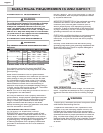
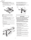
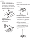
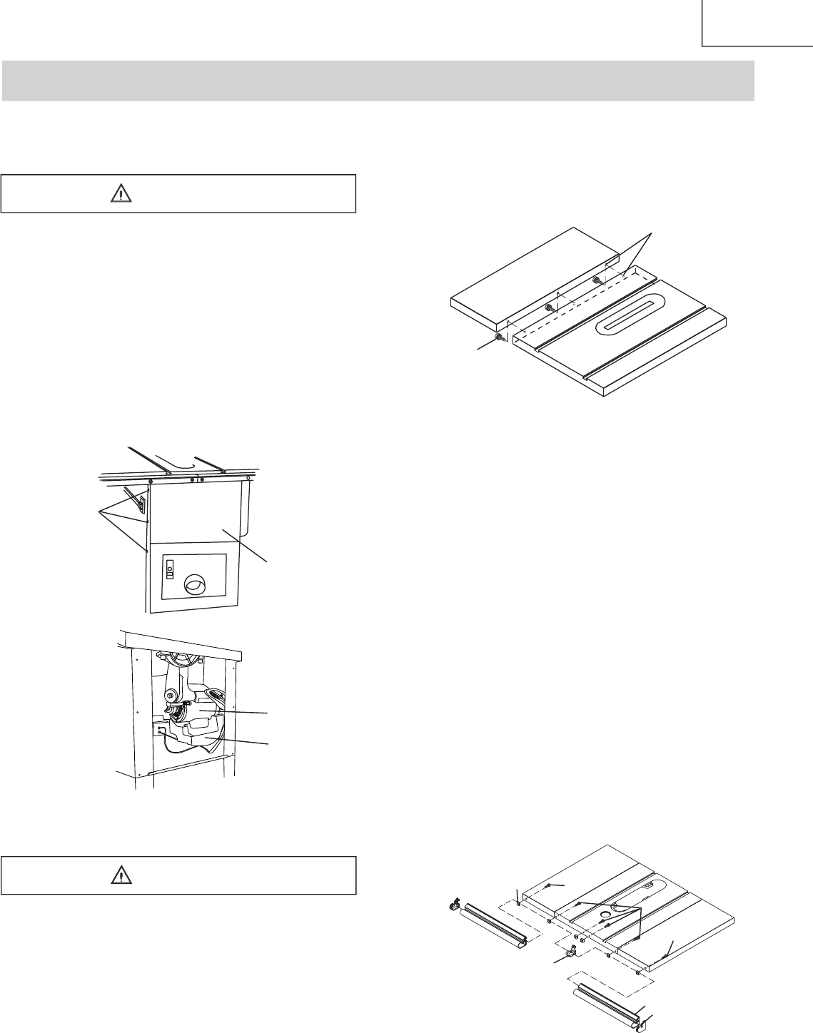
4. Adjust the mounting bolts (2) until the extension is
fl ush with the saw table. Tighten.
5. Repeat these procedures for the right extension
table.
Fig.
B
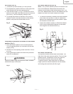
ASSEMBLY THE FRONT AND REAR TABLE RAIL
(FIG. B-1, B-2)
NOTE:
Front of table rails assemblies are different.
Assembly the front rail (Fig. B-1)
1. Attach the right front side cover (1) into right front
table rail (2). Repeat for the left front rail.
2. Place the hex. bolts M8-20 (3), hex bolts M8-16 (4)
through the holes at the front table edge. Screw the
square nuts (5) onto each bolts.
NOTE
: Keep the bolts and square nuts loosened
before front rail fi xed.
3. Attach the right front rail onto proper location by
having the square nuts pass through the slot of the
front rail. Repeat for the left front rail.
4. Attach the middle plug (6) to connect the two half
front rail.
5. When the blade was installed, use the rip fence and
gauge to adjust the front rail to proper location. When
the front rail is level with table, then fi x the front rail
by tightening the six bolts.
Fig.
B-1
R
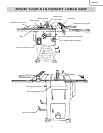
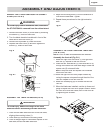
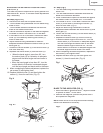
EMOVE
THE STYROFOAM FROM THE CABINET-
STAND (FIG. A & A-1)
To avoid injury from an accidental start, make sure
the STYROFOAM is removed from the cabinet stand.
1. Remove the back cover (2) of the base by removing
the screws (1), three for each side.
2. Turn the blade elevation handwheel in front of the
table saw to raise the motor (3).
3. Remove the styrofoam (4) under the motor.
4. Replace the back cover (2) and then tighten the
screws (1), three for each side.
Fig. A
Fig. A-1
ASSEMBLY THE TABLE EXTENSION (FIG. B)
To avoid injury, beware the weight of the table
extension before assembling the table extension.
1. Place the left table extension next to the saw table,
aligning the mounting holes (1).
2. Place bolts (2) and thread in mounting holes.
3. Place a straight edge or combination square on the
saw table, across the table extension.
2
1
ASSEMBLY AND ADJUSTMENTS
4
4
3
5
6
1
2
WARNING
1
2
3
4
WARNING