


–
16
–
English
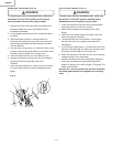
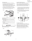
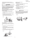
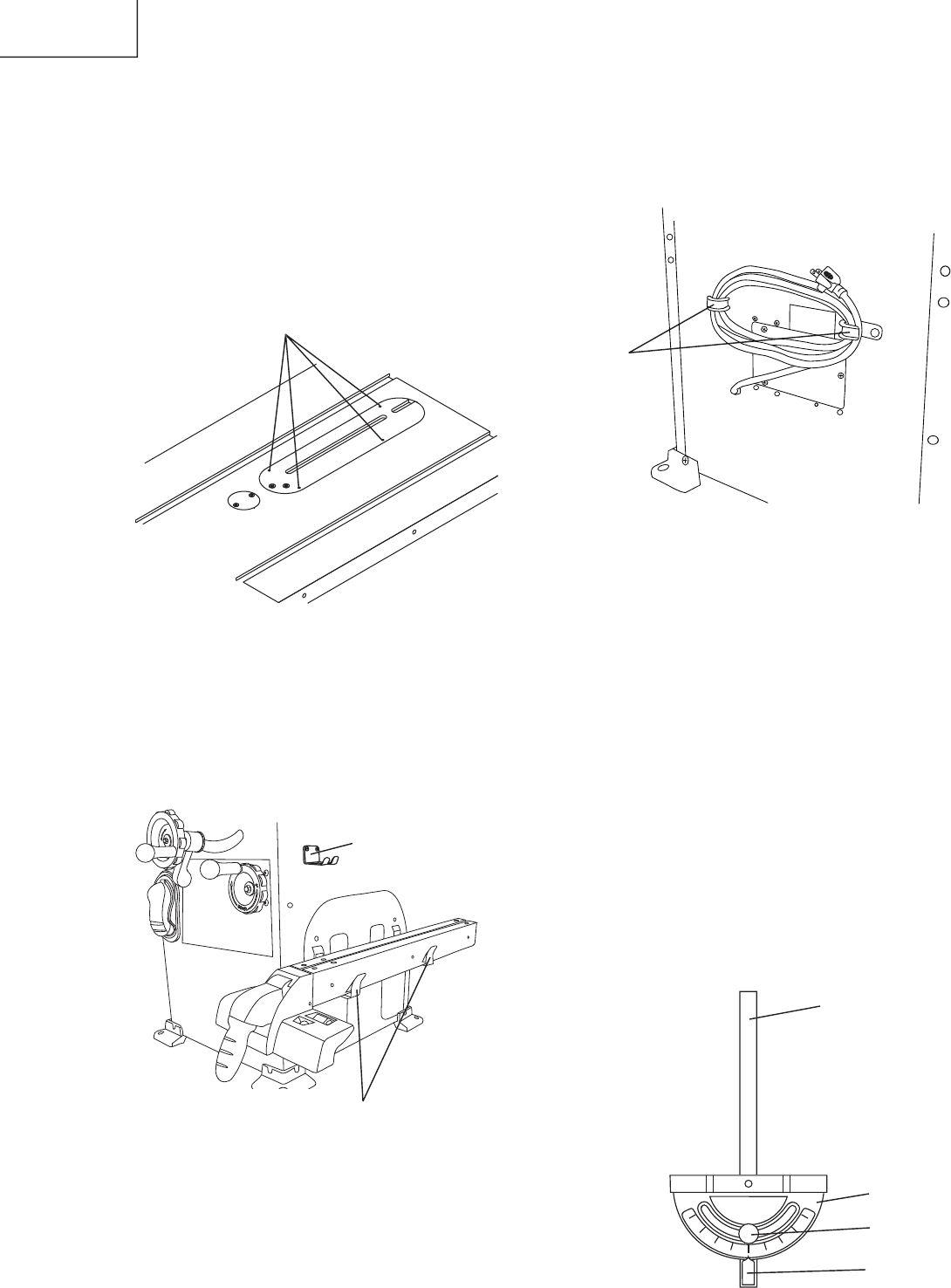
Power Cord
(FIG. M)
For convenience and to prevent damage to the power
cord when the table saw is not in use or is being
transported, the frame of leg has two brackets (1) on the
side for cord storage.
Fig.
M
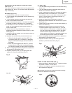
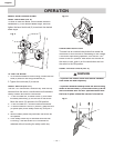
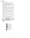
MITER
GAUGE ADJUSTMENT (FIG. N)
1. Make sure that the miter gauge bar (1) will slide
freely through the table top grooves.
2. Loosen the lock knob handle (2) and turn the gauge
body (3) to set the pointer (4) at 0
O
on the scale.
3. Make a 90
O
cut in a scrap piece of wood. Check
the cut to see if it is 90
O
. If not, loosen the lock knob
handle (2) and move the miter gauge body until it is
square to the miter gauge bar by using a combination
square.
MITER
GAUGE OPERATION (FIG. N)
The miter gage is accurately constructed with index
stops at 0
O
, 15
O
, 30
O
, 45
O
, 60
O
both right and left side.
The operate the miter gage, simply loosen the lock
handle (2) and move the body of the miter gauge to the
desired angle. The miter gauge body will stop at 0
O
, 15
O
,
30
O
, 45
O
, 60
O
both right and left side.
Fig.
N
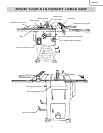
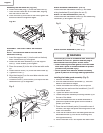
STORAGE (FIG. L, M)
Rip fence and miter gauge (Fig. L)
Storage brackets for the rip fence (1) and miter
gauge (2) are located on the right side of the saw
housing and frame of leg.
Fig.
L
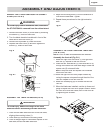
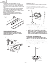
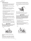
INSTALLING THE TABLE INSERT
(FIG. K)
The table insert has been previously installed on your
unit. However, you must verify that the table insert is
fl ush with the table top surface on all four corners of the
insert.
To avoid serious injury, the table insert must be level
with the table.
If the table insert is not fl ush with the
table, adjust the four bolts (1) with a 4 mm hex. wrench
until it is parallel with the table.
NOTE
: To raise the insert, turn the hex screws
counterclockwise, to lower the insert, turn the hex
screws clockwise.
Fig.
K
1
3
2
4
1
1
2
1