


To avoid injury, turn the switch OFF and unplug the band
saw from the power source before making any adjustments.
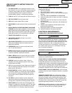
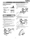
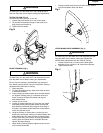
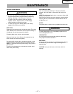
TILTING THE SAW (Fig. H)
The band saw body (1) tilts 0° to 45° left.
1. Loosen body lock handle (2) on rear of saw body.
2. Tilt the table to the desired angle on the scale (3) on
body using crank handle (4).
3. Tighten the lock handle.
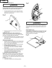
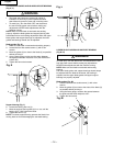
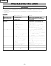
BLADE TRACKING (Fig. I)
To avoid injury, turn the switch OFF and disconnect the saw
from the power source before making any adjustments.
Be very careful; improperly tracked blade may spring out
from wheels causing serious injury. Do not perform tracking
adjustment while band saw is running.
1. Open body door.
2. To check the blade tracking, rotate drive wheel by hand
in clockwise direction.
3. Proper tracking is achieved when drive and idler wheels
are aligned. Tracking plate (1) on the back of the tool
frame is used to tilt upper idler wheel and align all
three blade wheels.
4. Loosen up hex nut (2).
5. Loosen up socket head bolts (3). There are four socket
head bolts holding tracking plate. Bottom socket head
bolts should be loosened just enough to allow tilting of
the plate. If the bottom socket head bolt is loosened too
much, the plate will not tilt.
6. Using set screws, (4) tilt the plate in vertical (up and
down) plane until proper tracking is achieved. Upper idler
blade wheel tilts in the same direction as tracking plate.
• If blade rides away from cabinet, increase gap between
tracking plate and cabinet wall. If the blade rides into
cabinet, decrease the gap.
• When blade is tracking properly, tighten up hex nut and
all four socket head bolts.
• Properly tracked blade should ride at the center position
on all three wheels (drive and idlers).
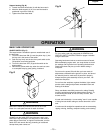
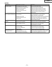
UPPER BLADE GUIDE ASSEMBLY (Fig. J)
To avoid injury, turn the switch OFF and disconnect the saw
from the power source before making any adjustments.
NEVER make adjustments with the machine running.
1. Loosen the lock knob (1) and move the blade guide
assembly (2) up or down to 1/8″ above the workpiece.
2. Tighten the lock knob.
WARNING
WARNING
WARNING
English
– 13 –
Fig. H
2
4
1
3
Fig. I
1
4
Fig. J
1
2
2
3