


14
English
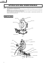
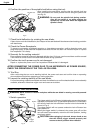
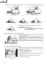
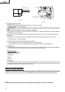
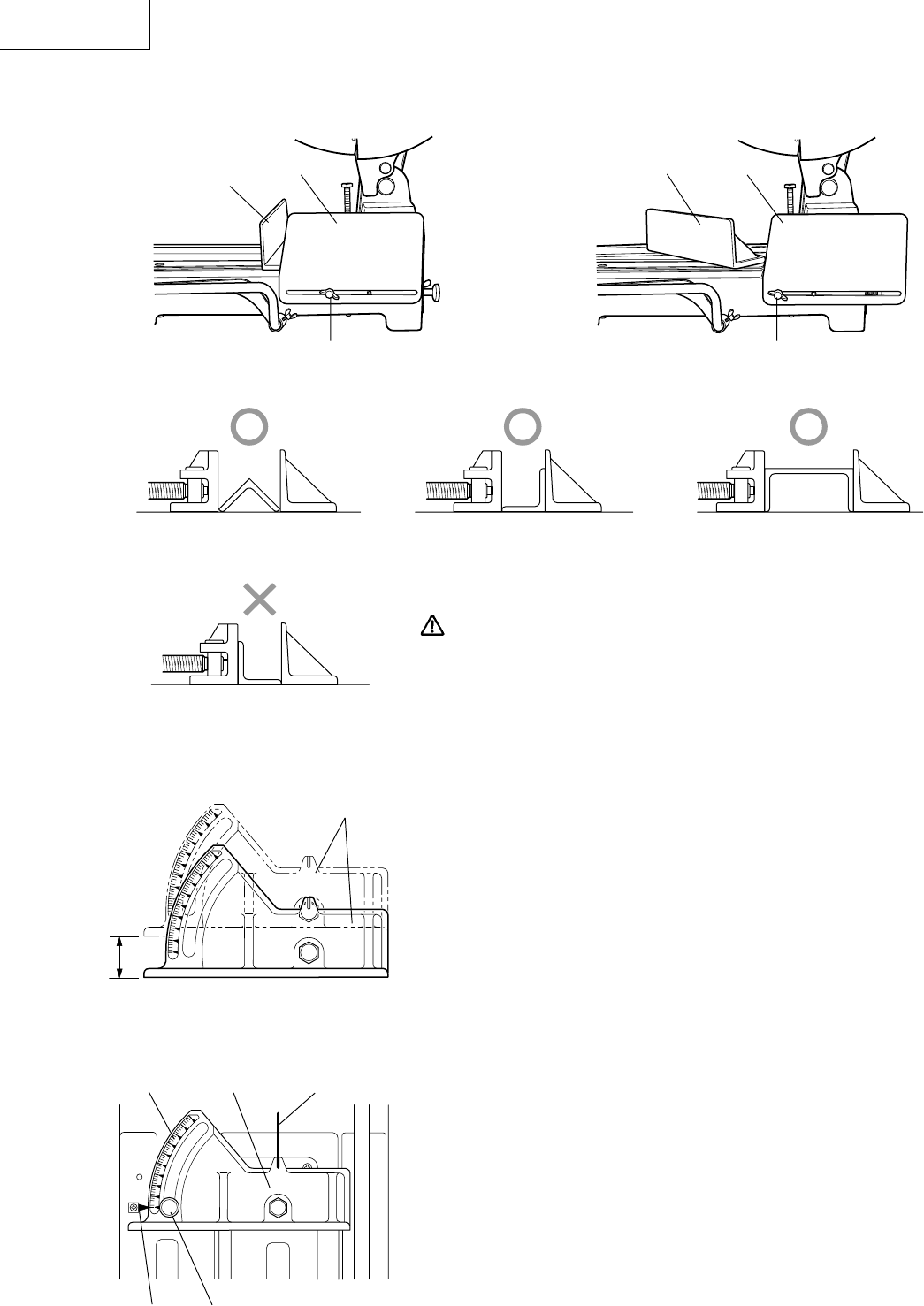
Untighten the wing bolt and move the side cover so that it is in alignment with the angle set. (Fig. 11)
Fig. 11
Fig. 12
Cutting Material in case of angle or channel, to fix as Fig. 12
WARNING: Never fix as Fig. 13
If it is, the cutting material will move and cutting
accuracy will deteriorate.
Fig. 13
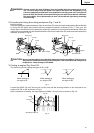
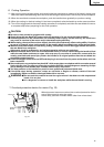
4. Moving the stationary vise-jaw (Fig. 14)
The vise opening is set at the maximum of 7-5/16" (186 mm) when
shipped from the factory.
In case an opening more than 7-5/16" (186 mm) is required, move
the vise-jaw to the position shown by the chain line, after
unscrewing the two bolts. The maximum opening can be set in
8-17/32" (217 mm).
When the material to be cut is excessively wide, the vise can be
effectively used by repositioning the stationary side of the vise jaws.
Fig. 14
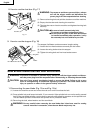
5. How to adjust 0 positon (Fig. 15)
The indicator is suitable for 0 positon of scale when shipped from
factory.
In case the vise (B) opening is move from 7-5/16" (186 mm) to
8-17/32" (217 mm) and so on.
Make adjust of 0 position as follows.
(1) Loosen M10 machine screw
(2) Adjust that white line of vise (B) is suitable for white line of
base.
(3) Adjust that indicator is suitable for 0 positio of scale
(4) Tighten loosened screw
Fig. 15
Vise (B) Side Cover
Wing Bolt
Vise (B)
Side Cover
Wing Bolt
Vise (B)
White LineVise (B)
Scale
Indicator M10 Machine Screw