


English
7
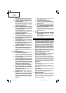
ASSEMBLY AND OPERATION
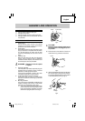
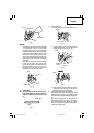
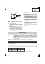
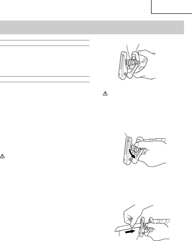
Lever
Front Cover
Fig. 2
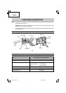
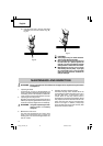
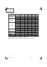
APPLICATIONS
⅜
Cutting metal and stainless steel pipe.
⅜
Cutting various lumber.
⅜
Cutting mild steel, aluminum and copper plate.
⅜
Cutting synthetic resins, such as phenol resin and
vinyl chloride.
PRIOR TO OPERATION
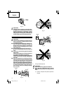
1. Power source
Ensure that the power source to be utilized
conforms to the power source requirements
specified on the product nameplate.
2. Power switch
Ensure that the switch is in the OFF position. If the
plug is connected to a receptacle while the switch
is in the ON position, the power tool will start
operating immediately and can cause serious
injury.
3. Extension cord
When the work area is far away from the power
source, use an extension cord of sufficient
thickness and rated capacity. The extension cord
should be kept as short as practicable.
WARNING:
Damaged cord must be replaced
or repaired.
4. Check the receptacle
If the receptacle only loosely accepts the plug, the
receptacle must be repaired. Contact a licensed
electrician to make appropriate repairs.
If such a faulty receptacle is used, it may cause
overheating, resulting in a serious hazard.
5. Confirming condition of the environment:
Confirm that the work site is placed under
appropriate conditions conforming to prescribed
precautions.
6. Mounting the blade
This unit employs a detachable mechanism that
enables mounting and removal of saw blades
without the use of a wrench or other tools.
(1) Turn on and off the switching trigger several
times so that the lever can jump out of the
front cover completely. Thereafter, turn off the
switch and unplug the power cord. (Fig. 2)
CAUTION:
Be absolutely sure to keep the switch turned
off and the power cord unplugged to prevent
any accident.
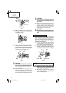
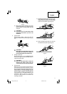
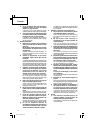
(2) Push the lever in the direction of the arrow
mark shown in Fig. 3 marked on the lever.
(3) Insert the saw blade all the way into the small
slit of the plunger tip with the lever pushing.
You can mount this blade either in the upward
or downward direction. (Fig. 4, Fig. 5)
Lever
Fig. 3
Fig. 4
Slit of
Plunger
Blade
01Eng_CR13V2_US 10/22/08, 18:087