


15
English
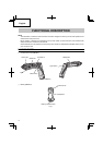
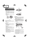
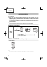
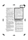
CAUTION
● The clutch dial cannot be set between the
numbers “1, 5, 9 ... 21” or the black dot.
● Do not use with the clutch dial set at the
line between the number “21” and the drill
mark “
”. Doing so may cause damage
(See Fig. 9).
Line
Triangle mark
Drill mark
Fig. 9
7. Tightening torque adjustment.
(1) Tightening torque
Tightening torque should correspond in its
intensity to the screw diameter. When too
strong power is used, the screw head may be
broken or be injured.
Be sure to adjust the clutch dial position
according to the screw diameter.
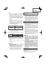
(2) Tightening torque indication (See Fig. 8)
The tightening torque diff ers depending on the
type of screw and the material being tightened.
The unit indicates the tightening torque with the
numbers “1, 5, 9 ... 21” and black dots on the
clutch dial. The tightening torque at position “1”
is the weakest and the torque is strongest at the
highest number.
(3) Adjusting the tightening torque (See Fig. 8)
Rotate the clutch dial and line up the numbers
“1, 5, 9 ... 21” or the dots on the clutch dial, with
the triangle mark on the outer body. Adjust the
clutch dial in the weak or the strong torque
direction according to the torque you need.
CAUTION
● The motor rotation may be locked to
cease while the unit is used as drill. While
operating the driver drill, take care not to
lock the motor.
● When setting the shift knob to “HIGH” (high
speed) and the position of the clutch dial is
between “9” and “21”, it may happen that
the clutch does not engaged and that the
motor is locked. In such a case, please set
the shift knob to “LOW” (low speed).
● If the motor is locked, immediately turn the
power off . If the motor is locked for a while,
the motor or battery may be burnt.
● Too long hammering may cause the screw
broken due to excessive tightening.
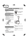
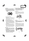
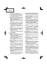
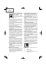
8. Switch operation
(1) Lock switch
The tool is equipped with a lock switch. To
activate the main switch lock, move the lock
switch to the “▼ LOCK” position. Move the lock
switch to the opposite position to operate the
tool. (Fig. 10)
Unlock
“▼ LOCK”
Lock switch
Lock
Fig. 10
CAUTION
Always set the lock switch to the “▼ LOCK”
position when carrying or storing the tool
eliminate unintentional starting.
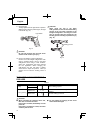
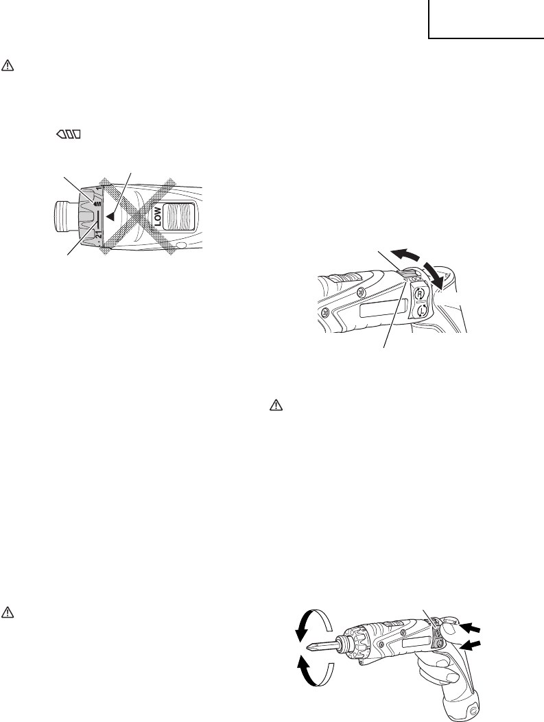
(2) Main switch
The main switch functions as a motor switch
and rotational direction selector switch. When
the main switch is pushed to “R” indicated on
the main switch, the bit rotates clockwise. When
the main switch is pushed to “L” indicated on the
main switch, the bit rotates counterclockwise.
When the main switch is released, the tool
stops. (Fig. 11)
R
L
Main switch
R
L
Fig. 11