


2
English
HOW TO USE THE ROUTER
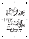
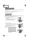
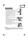
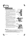
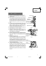
1. Adjusting depth of cut (Fig. 4)
(1) Place the tool on a flat wood surface.
(2) Turn the stopper block so that section to which
the cutting depth setting screw on stopper block
is not attached comes to the bottom of the stopper
pole. Loosen wing bolt, allowing the stopper pole
to contact with stopper block.
(3) Press the lock lever down and lower the tool body
until the bit just touches the flat surface. Release
the lock lever to hold the tool body down.
(4) Tighten wing bolt. Align the depth indicator with
the “0” graduation.
(5) Loosen wing bolt, and raise until indicator aligns
with the graduation representing the desired
cutting depth.
(6) Press the lock lever and press the tool body down
until the stopper block to obtain the desired cutting
depth.
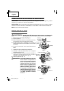
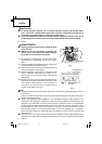
2. Stopper block (Fig. 5)
The two cut-depth setting screws attached to the
stopper block can be adjusted to simultaneously
set three different cutting depths. Use a wrench
to tighten the nuts so that the cut-depth setting
screws do not come loose at this time.
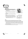
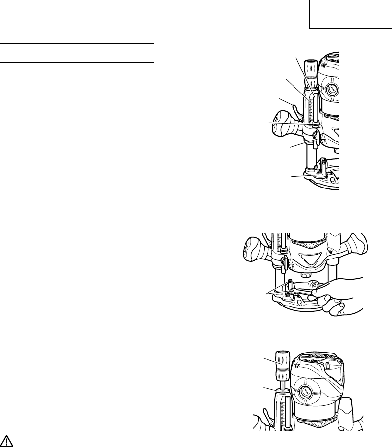
3. Upper limiting nuts (Fig. 6)
By turning the upper limiting nuts, the upper limit
of the tool body can be adjusted, when the tip of
the bit is retracted more than required in relation
to the base plate surface, turn the upper limiting
nuts to lower the upper limit.
CAUTION:
ⅷ The upper limiting nut (A) and upper limiting nut (B) must always be “jammed” together
to prevent movement (caused by vibration) which could prevent full bit retraction.
ⅷ The upper limiting nuts must always be set so that bit can be retracted into base of
router, clear of work.
Fig. 6
Limiting
Nut (B)
Limiting
Nut (A)
Stopper Pole
Fig. 4
Graduation
Lock Lever
Depth
Indicator
Wing Bolt
Stopper Block
Fig. 5
Cut Depth
Setting
Screw
01Eng_PlungeBase_US 9/5/07, 20:102