


19
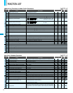
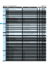
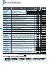
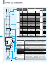
PROTECTIVE FUNCTIONS
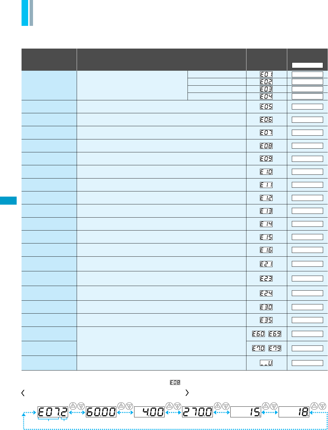
Name
Display on digital
operator
Display on remote
operator/copy unit
Cause(s)
Over-current
protection
Overload
protection(*1)
Braking resistor
overload protection
Over-voltage
protection
EEPROM error(*2)
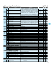
Under-voltage
error
CT(Current
transformer) error
CPU error
External trip
USP error
Ground fault
Input over-voltage
protection
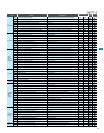
Instantaneous
power failure
Expansion card 1
connection error
Expansion card 2
connection error
Inverter thermal
trip
Missing phase
IGBT error
Thermistor error
Out of operation
due to under-voltage
An error has been detected in an expantion card or at its connecting terminals.
One of three lines of 3-phase power supply is missing.
While at constant speed
During deceleration
During acceleration
Others
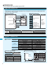
(*1)
You can clear the error by pressing the Start / Reset key 10 seconds after the trip occurred.
(*2)
If an EEPROM error occurs, be sure to confirm the parameter data values are still correct.
When the built-in EEPROM memory has problems due to noise or excessive temper-
ature, the inverter trips and turns off its output.
When a malfunction in the built-in CPU has occurred, the inverter trips and turns off
its output.
When a signal to an intelligent input terminal configured as EXT has occurred, the
inverter trips and turns off its output.
The inverter is protected by the detection of ground faults between the inverter output
and the motor during power-up tests. This feature protects the inverter only.
When the input voltage is higher than the specified value, it is detected 60 seconds
after power-up and the inverter trips and turns of its output.
When instantaneous over-current has occurred, the inverter trips and turns off its
output to protect main circuit element.
When the thermistor inside the motor detects temperature higher than the specified
value, the inverter trips and turns off its output.
When the DC bus voltage exceeds a threshold, due to regenerative energy from
the motor, the inverter trips and turns off its output.
When a motor overload is detected by the electronic thermal function, the inverter
trips and turns off its output.
The inverter output was short-circuited, or the motor
shaft is locked or has a heavy load.
These conditions cause excessive current for the
inverter, so the inverter output is turned off.
When the regenerative braking resistor exceeds the usage time allowance or an over-voltage caused by the
stop of the BRD function is detected, the inverter trips and turns off its output.
A decrease of internal DC bus voltage below a threshold results in a control circuit fault. This condition can
also generate excessive motor heat or cause low torque. The inverter trips and turns off its output.
If a strong source of electrical interference is close to the inverter or abnormal operations occur in the built-
in CT(Current transformer), the inverter trips and turns off its output.
An error occurs when power is cycled while the inverter is in RUN mode if the Unattended Start Protection
(USP) is enabled. The inverter trips and does not go into RUN mode until the error is cleared.
When power is cut for more than 15msec., the inverter trips and turns off its output. If power failure contin-
ues, the error will be cleared. The inverter restarts if it is in RUN mode when power is cycled.
When the inverter internal temperature is higher than the specified value, the thermal sensor in the inverter
module detects the higher temperature of the power devices and trips, turning off the inverter output.
Gate array error
Communication error has occured between CPU and gate array.
Due to insufficient voltage, the inverter has turned off its output and been trying to
restart. If it fails to restart, it goes into the under-voltage error.
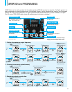
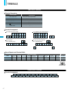
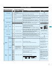
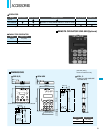
How to access the details about the present fault
Status at trip pointError code
Output frequency
at trip point
Motor current
at trip point
Voltage between
P(+) and N(–) at trip point
Cumulative inverter
operation (run) time
at trip point
Cumulative power-on
time at trip point
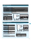
OC.Drive
ERR1****
OC.Drive
OC.Accel
Over.C
Over.L
OL.BRD
Over.V
EEPROM
Under.V
CT
CPU1
EXTERNAL
USP
GND.Flt.
OV.SRC
Inst.P-F
OP1 0-9
OP2 0-9
OH FIN
GA
PH.Fail
IGBT
TH
UV.WAIT
–
–