


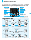
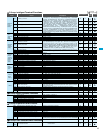
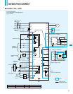
20
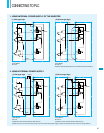
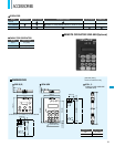
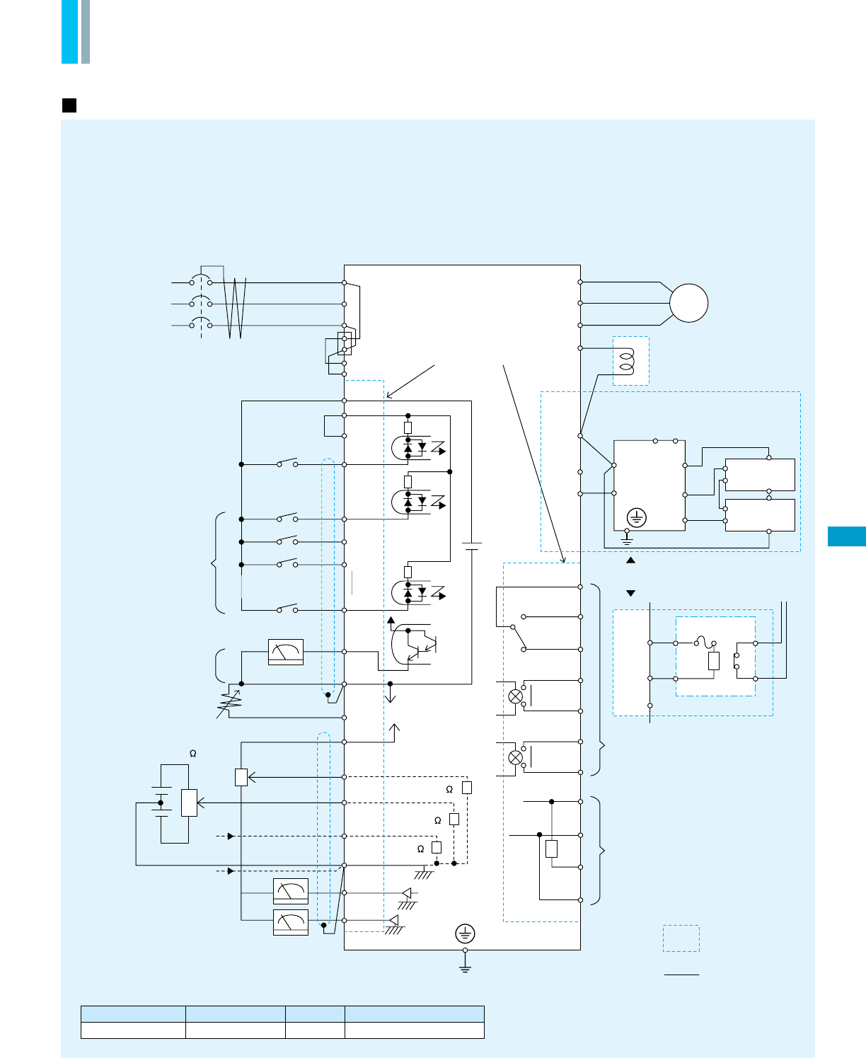
CONNECTING DIAGRAM
200V
-
240V 10%
50/60Hz 5%
Short-circuit bar
Forward command
Intelligent
input terminals
(5 terminals)
Thermistor
DC0
-
10V(12-bit)
DC0
-
10V
(8-bit)
DC4
-
20mA
(8-bit)
(G)
DC
–
10
–+
10V
(12-bit)
Current input
4
-
20mA
(12-bit)
Analog input
Analog output
FM Monitor output
(PWM)
RS485
Serial communication port
Intelligent output terminals
DC link choke
IM
Removable terminals
L300P
R
(
L1
)
S
(
L2
)
T
(
L3
)
R0
P24
PLC
CM1
FW
5
4
3
1
FM
CM1
O2
OI
L
AM
AMI
10k
10k
100
TH
H
O
T0
SN
RP
SN
SP
12C
12A
11C
P
RB
P
RB
N
Braking resistor (RB)
11A
AL2
AL1
AL0
NN
P
AL1
Dynamic braking unit (BRD)
AL2
RB
R1
R2
RB
P
(
+1
)
PD
(
T3
)
W
(
T2
)
V
(
T1
)
U
DC24V
DC10V
-
+
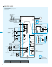
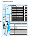
Terminal Name
Common
FW, 1, 2, 3, 4, 5
P24
FM, TH
CM1
H, O, O2, OI, AM, AMI
L
AL1
AL2
AL1
AL2
RB
P
RB
P
(+)
(
-
)
(Inverter)
(To operating circuit)
For 18.5kW(25HP) and over
For up to 15kW(20HP)
In case of 400V class,
place a transformer for operating circuit
to receive 200V.
Option
Customer wiring
(Outside the inverter)
SOURCE TYPE LOGIC
Frequency
setting device
500
-
2k
R
T
(
J51
)
(*
2
)
(*2)Remove connection with J51
when RoTo power is supplied
externally
Control power source