


English
13
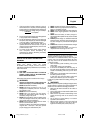
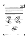
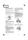
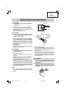
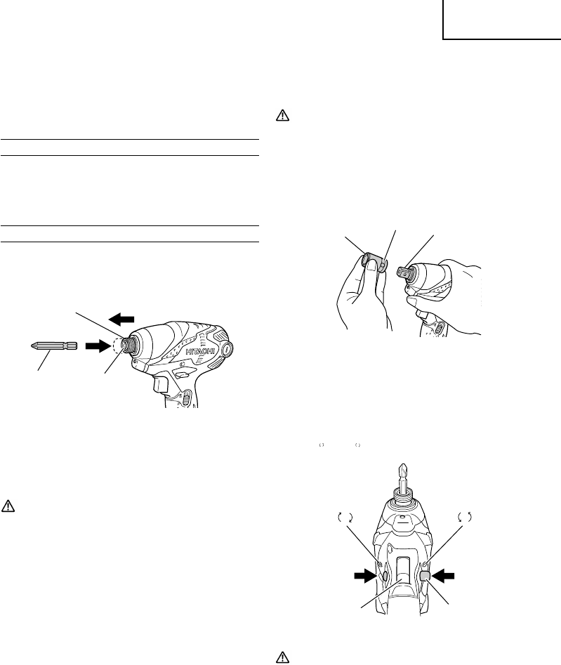
plunger, and mount the hex. socket on the anvil.
Check that the plunger is fully engaged in the hole.
When removing the socket, reverse the sequence.
CAUTION
●
Please use the designated attachments which are
listed in the operations manual and Hitachi’s
catalog. Accidents or injuries could result from
not doing so.
●
Make sure to firmly install the socket in the anvil.
If the socket is not firmly installed it might come
out and cause injuries.
Fig. 7
5. Confirm that the battery is mounted correctly.
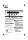
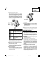
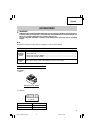
6. Check the rotational direction
The bit rotates clockwise (viewed from the rear side)
by pushing the R-side of the push button.
The L-side of the push button is pushed to turn the
bit counterclockwise. (See Fig. 8).
(The
L
and
R
marks are engraved on the body.)
R
L
Fig. 8
CAUTION
The push button can not be switched while the
impact driver is turning. To switch the push
button, stop the impact driver, then set the push
button.
7. Switch operation
⅜
When the trigger switch is depressed, the tool
rotates. When the trigger is released, the tool stops.
⅜
The rotational speed can be controlled by varying
the amount that the trigger switch is pulled. Speed
ⅷ
When the pilot lamp flickers rapidly in red (at 0.2–
second intervals), check for and take out any
foreign objects in the charger’s battery installation
hole. If there are no foreign objects, it is probable
that the battery or charger is malfunctioning. Take
it to your authorized Service Center.
BEFORE USE
Check the work area to make sure that it is clear of debris
and clutter.
Clear the area of unnecessary personnel. Ensure that
lighting and ventilation is adequate.
OPERATION
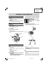
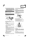
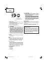
1. Installing the bit (WH18DSDL)
Always follow the following procedure to install
driver bit. (Fig. 6)
Fig. 6
(1) Pull the guide sleeve forward.
(2) Insert the bit into the hexagonal hole in the anvil.
(3) Release the guide sleeve and it returns to its origianl
position.
CAUTION
If the guide sleeve does not return to its original
position, then the bit is not installed properly.
2. Removing the bit (WH18DSDL)
Please do the opposite point on the method of
installing bit.
3. Selecting the socket matched to the bolt
(WR18DSDL)
Be sure to use a socket which is matched to the bolt
to be tightened. Using an improper socket will not
only result in insufficient tightening but also in
damage to the socket or nut.
A worn or deformed hex. or square-holed socket will
not give an adequate tightness for fitting to the nut
or anvil, consequently resulting in loss of tightening
torque.
Pay attention to wear of socket hole, and replace
before further wear has developed.
4. Installing a socket (WR18DSDL)
Select the socket to be used.
ⅷ
Plunger type (Fig. 7)
Align the plunger located in the square part of the
anvil with the hole in the hex. socket. Then push the
Hexagonal socket
Groove
Anvil
R
L
Trigger switch Push button
Push
Push
Movement
Driver bit
Hexagonal hole
in the anvil
Guide sleeve
01Eng_WH18DSDL_US.p65 10/2/12, 2:38 PM13