


6
English
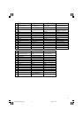
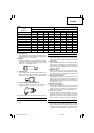
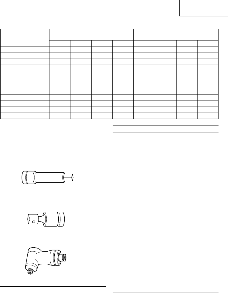
Table 1 B = 12.7 mm
Socket
Ordinary Socket Long Socket
Designation
Dimension (mm) Dimension (mm)
Hex. Socket 12
13
14
17
19
21
22
23
24
26
27
30
S
17
19
21
22
23
24
26
27
30
D
28
28
32
35
36
38
38
42
42
E
15
17
19
24
25
25
25
24
34
L
32
34
36
40
40
40
40
40
50
S
12
13
14
17
19
21
22
23
24
26
27
30
D
20
21.5
22
25
28
31
32.5
33
34
38
40
42
E
34
34
34
34
34
34
34
34
34
57
57
57
L
52
52
52
52
52
52
52
52
52
75
75
75
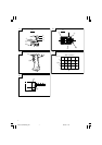
2. Extension bar
The extension bar is convenient for working in very
restricted spaces or when the socket provided cannot
reach the bolt to be tightened.
CAUTION
When the extension bar is used the tightening torque
is reduced slightly compared with the ordinary
socket. So it is necessary to operate the tool a little
longer to get the same torque.
3. Universal joint
The universal joint is convenient for impacting nuts
when there is an angle between the socket and
wrench, or when working in a very narrow space.
4. Corner attachment (Model EW-14R)
Use this attachment only when the machine is
applied to the nut or bolt at a right angle.
Optional accessories are subject to change without notice.
APPLICATIONS
⅜ Tightening and loosening various kinds of bolt and
nut.
PRIOR TO OPERATION
1. Power source
Ensure that the power source to be utilized conforms
to the power requirements specified on the product
nameplate.
2. Power switch
Ensure that the power switch is in the OFF position.
If the plug is connected to a receptacle while the
power switch is in the ON position, the power tool
will start operating immediately, which could cause
a serious accident.
3. Extension cord
When the work area is removed from the power
source, use an extension cord of sufficient thickness
an rated capacity. The extension cord should be
kept as short as practicable.
4. Fixing the side handle
The position of the side handle attached to the
hammer case can be changed by unscrewing the
handle. (Right hand screw) Turn the handle to the
desired position for the job and secure the handle
by screwing up tight.
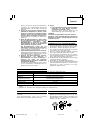
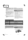
5. Mounting the socket
(1) Pin, O-ring type (Fig. 1)
Select a socket matched to the bolt to be tightened
or loosened. Insert the socket on the anvil of the
wrench, and secure it with the pin and ring. When
dismantling the socket, reverse the sequence.
(2) Plunger type (Fig. 2)
Align the plunger located in the square part of the
anvil with the hole in the hex socket. Then push
the plunger, and mount the hex socket on the anvil.
Check that the plunger is fully engaged in the hole.
When removing the socket, reverse the sequence.
HOW TO USE
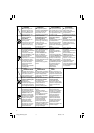
1. Operation of switch (Fig. 3)
The switch in this machine functions as a motor
switch and rotational direction selector switch. When
the switch is set to R indicated on the handle cover,
the motor rotates clockwise to tighten the bolt.
01Eng_WR16SA(S)_WE 4/7/10, 13:296