


10
Starting from halfway, without pulling back, causes
the safety cover to be caught in the cutting groove of
the workpiece and to contact the saw blade.
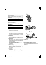
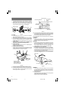
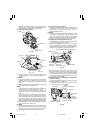
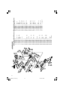
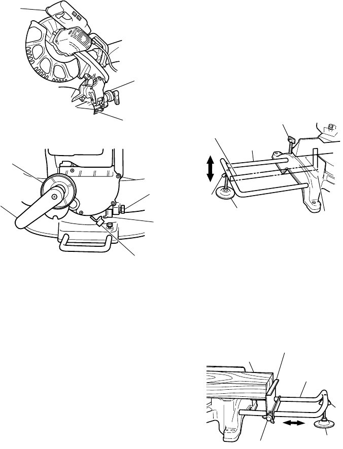
12.Bevel angle fine adjustment
Fig. 20
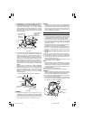
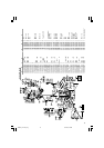
Fig. 21
(1) Grip the handle on the motor head and position it at
the bevel angle you need. Temporarily tighten the
clamp lever.
CAUTION
⅜ If not tightened firmly enough the motor head might
suddenly move or slip, causing injuries. Be sure to
tighten the motor head section enough so it will not
move.
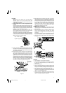
(2) Make fine adjustments to the bevel angle by gripping
the handle and moving the knob (A).
NOTE
⅜ Turning knob (A) clockwise, allows fine adjustment
of the main unit to the left (as seen from front).
Turning knob (A) counterclockwise, allows fine
adjustment of the main unit to the right (as seen from
front).
If you tilt the main unit in the direction that does not
place a load on plate (A) and pull plate (A), the contact
position changes and the right slope angle becomes 3°.
If you tilt the main unit in the direction that does not
place a load on plate (B) and pull plate (B), the contact
position changes and the right slope angle becomes 48°.
(3) After adjusting to the desired angle, tighten the clamp
lever and clamp the motor head.
CAUTION
⅜ Always check that the clamp lever is secured and the
motor head is clamped. If you attempt angle cutting
without clamping the motor head, then the motor
head might shift unexpectedly causing injuries.
13.Compound cutting procedures
Compound cutting can be performed by following the
instructions in 10 and 11 above. For maximum
dimensions for compound cutting, refer to
“SPECIFICATIONS” table.
CAUTION
⅜ Always secure the workpiece with the right hand side
for compound cutting. Never rotate the table to the
right for compound cutting, because the saw blade
might then contact the clamp or vise that secures the
workpiece, and cause personal injury or damage.
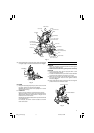
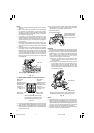
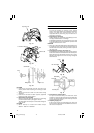
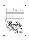
14.Installing the holders (Optional accessory)
The holders help keep longer workpieces stable and
in place during the cutting operation.
(1) As indicated in Fig. 22, use a steel square for aligning
the upper edge of the holders with the base surface.
Loosen the 6 mm wing nut. Turn a height adjustment
bolt 6 mm, and adjust the height of the holder.
Fig. 22
(2) After adjustment, firmly tighten the wing nut and
fasten the holder with the 6 mm knob bolt (optional
accessory). If the length of Height Adjustment Bolt 6
mm is insufficient, spread a thin plate beneath. Make
sure the end of Height Adjustment Bolt 6 mm does
not protrude from the holder.
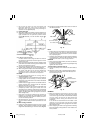
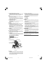
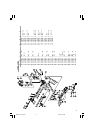
15. Stopper for precision cutting (Stopper and holder are
optional accessory)
The stopper facilitates continuous precision cutting
in lengths of 280 mm to 450 mm.
To install the stopper, attach it to the holder with the
6 mm wing bolt as shown in Fig. 23.
Fig. 23
Handle
Knob (A)
8 mm bolt (B)
Clamp lever
Knob (A)
8 mm bolt (A)
Plate (A)
Plate (B)
Steel Square
Holder
(Optional accessory)
6 mm Wing Bolt (Optional accessory)
Base Surface
Height Adjustment
Bolt 6 mm
(Optional accessory)
6 mm
Wing Nut
(Optional
accessory)
Workpiece
Stopper
(Optional accessory)
Holder
(Optional accessory)
6 mm Wing
Nut
(Optional
accessory)
Height Adjustment Bolt 6 mm
(Optional accessory)
6 mm Wing Bolt
(Optional accessory)
01Eng_C12LCH_Eng 4/11/07, 6:55 PM10