


6
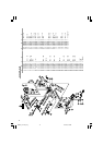
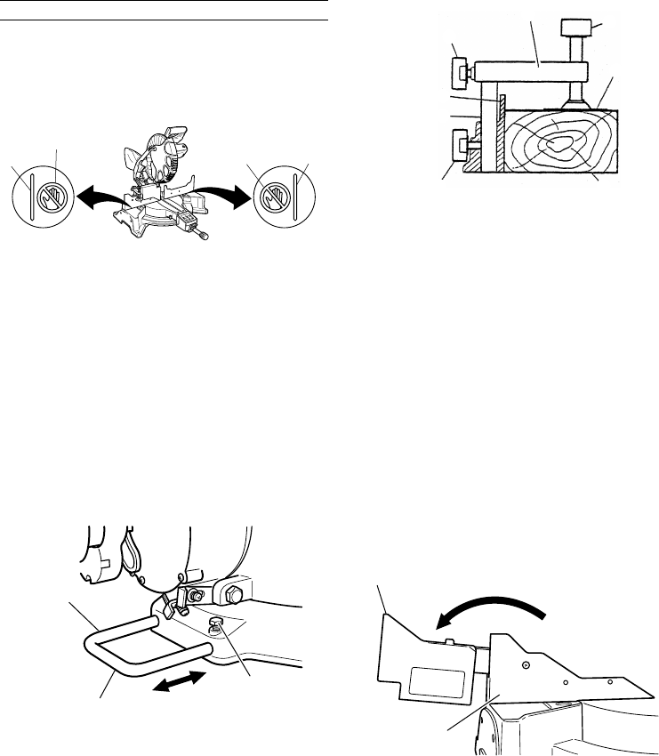
Fig. 7
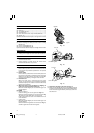
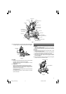
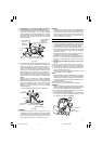
(2) The screw holder can be raised or lowered according
to the height of the workpiece by loosening the 6 mm
wing bolt (B). After the adjustment, firmly tighten the
6 mm wing bolt (B) and fix the screw holder.
(3) Turn the upper knob and securely fix the workpiece
in position.
WARNING
⅜ Always firmly clamp or vise to secure the workpiece
to the fence; otherwise the workpiece might be thrust
from the table and cause bodily harm.
CAUTION
⅜ Always confirm that the motor head does not contact
the vise assembly when it is lowered for cutting. If
there is any danger that it may do so, loosen the 6
mm wing bolt and move the vise assembly to a
position where it will not contact the saw blade.
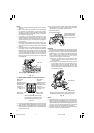
5. Confirmation for use of sub fence
This power tool is equiped with a sub fence (See Fig. 2).
In the case of direct angle cutting and angle cutting,
use the sub fence. Then you can realize stable cutting
of the material with a wide back face.
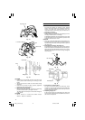
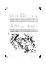
In the case of left bavel cutting, raise the sub fence up
as illustrated in Fig. 8 and then turn it counterclockwise.
Fig. 8
WARNING
In the case of left bevel cutting, turn the sub fence
counterclockwise. Unless it is turned counterclockwise,
the main bady or saw blade may contact the sub fence,
resulting in an injury.
6. Using an ink line
Upon lowering the motor section, the lower guard is
raised and the saw blade appears.
Align the ink line with the saw blade.
Move
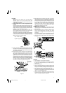
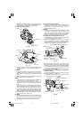
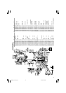
Adjust the holder
until its bottom
surface contacts the
work bench surface.
Holder (B)
6 mm Bolt
6 mm Wing Bolt (B)
Screw Holder
Knob
Vise Plate
Workpiece
6 mm Wing Bolt (A)
Vise Shaft
Fence (B)
PRACTICAL APPLICATIONS
WARNING
⅜ To avoid personal injury, never remove or place a
workpiece on the table while the tool is being operated.
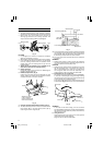
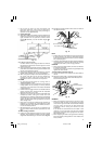
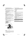
⅜ Never place your limbs inside of the line next to
warning sign while the tool is being operated. This
may cause hazardous conditions (see Fig. 5).
Fig. 5
CAUTION
⅜ It is dangerous to remove or install the workpiece
while the saw blade is turning.
⅜ When sawing, clean off the shavings from the turntable.
⅜ If the shavings accumulate too much, the saw blade
from the cutting material will be exposed. Never
subject your hand or anything else to go near the
exposed blade.
1. Tightly secure the material by vise assembly to be
cut so that it does not move during cutting
2. Switch operation
Pulling the trigger turns the switch on. Releasing the
trigger turns the switch off.
3. Holder (B) adjustment (Fig. 6)
Loosen the 6 mm bolt with the supplied 10 mm box
wrench. Adjust the holder (B) until its bottom surface
contacts the bench or the floor surface.
Fig. 6
4. Using the Vise Assembly (Standard accessory) (Fig. 7)
(1) The vise assembly can be mounted on either the left
fence {Fence (B)} or the right fence {Fence (A)} by
loosening the 6 mm wing bolt (A).
Warning Sign
Line
Warning Sign
Line
Sub Fence
Turn
Fence (B)
01Eng_C12LCH_Eng 4/11/07, 6:55 PM6