


9
Marking
(pre-marked)
Marking
(pre-marked)
⅜ Do not use the main unit near equipment that
generates electrical noise such as generators.
Electrical noise might cause faulty readings or
operation on the digital display.
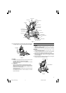
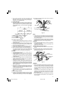
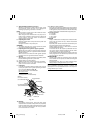
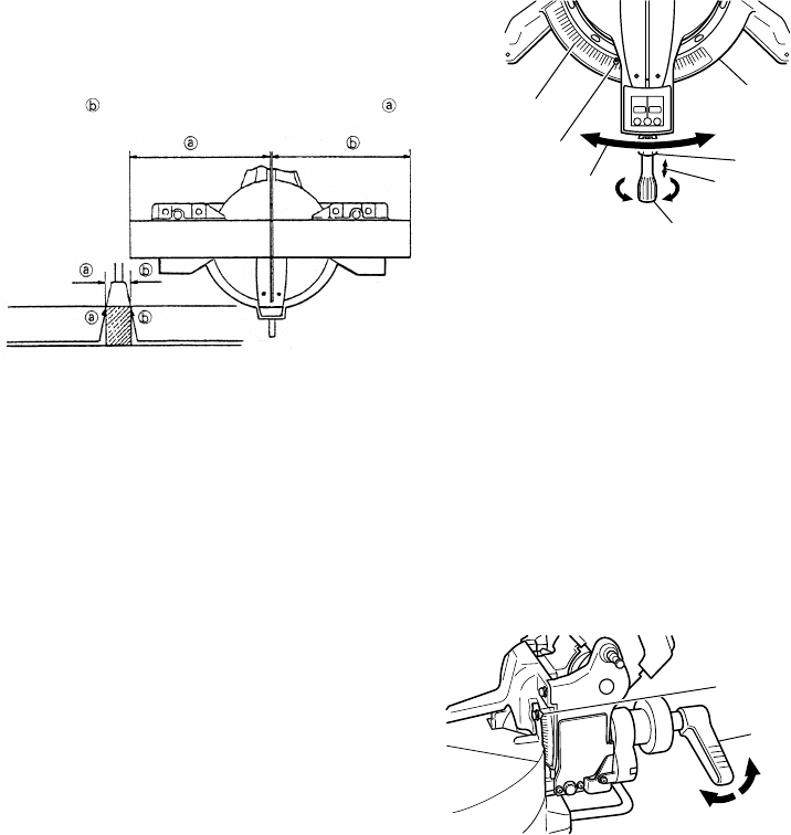
9. Cutting operation
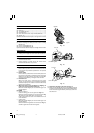
(1) As shown in Fig. 17 the width of the saw blade is the
width of the cut. Therefore, slide the workpiece to the
right (viewed from the operator’s position) when
length
is desired, or to the left when length is
desired.
Fig. 17
(Only Model C12LCH/C12FCH)
If a laser marker is used, align the laser line with the
left side of the saw blade, and then align the ink line
with the laser line.
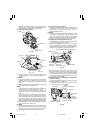
(2) Once the saw blade reaches maximum speed, slowly
push down the handle and bring the saw blade in the
vicinity of the material to be cut.
(3) Once the saw blade contacts the workpiece, push the
handle down gradually to cut into the workpiece.
(4) After cutting the workpiece to the desired depth, turn
the power tool OFF and let the saw blade stop
completely before raising the handle from the
workpiece to return it to the full retract position.
CAUTION
⅜ For maximum dimensions for cutting, refer to
“SPECIFICATIONS” table.
⅜ Increased pressure on the handle will not increase the
cutting speed. On the contrary, too much pressure
may result in overload of the motor and/or decreased
cutting efficiency.
⅜ Confirm that the trigger switch is turned OFF and the
power plug has been removed from the receptacle
whenever the tool is not in use.
⅜ Always turn the power off and let the saw blade stop
completely before raising the handle from the
workpiece. If the handle is raised while the saw blade
is still rotating, the cut-off piece may become jammed
against the saw blade causing fragments to scatter
about dangerously.
⅜ Every time one cutting of deep-cutting operation is
finished, turn the switch off, and check that the saw
blade has stopped. Then raise the handle, and return
it to the full retract position.
⅜ Be absolutely sure to remove the cut material from
the top of the turntable, and then proceed to the next
step.
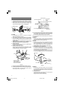
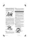
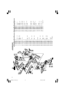
10.Miter cutting procedures
(1) Loosen the side handle and push the lever for angle
stoppers. Then, adjust the turntable until the indicator
aligns with desired setting on the miter scale (Fig. 18).
(2) Re-tighten the side handle to secure the turntable in
the desired position.
Fig. 18
NOTE
⅜ Positive stops are provided at the right and left of the
0° center setting, at 15°, 22.5°, 31.6° and 45° settings.
Check that the miter scale and the tip of the indicator
are properly aligned.
⅜ Operation of the saw with the miter scale and indicator
out of alignment, or with the side handle not properly
tightened, will result in poor cutting precision.
CAUTION
⅜ Never remove the side handle; use of the tool without
it would be hazardous.
To prevent an accident or personal injury always firmly
tighten the miter handle.
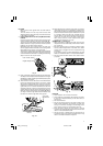
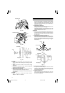
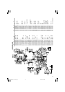
11.Bevel cutting procedures (Fig. 19)
(1) Loosen the clamp lever and bevel the saw blade to
the left.
(2) Adjust the bevel angle to the desired setting while
watching the bevel angle scale and indicator, then
secure the clamp lever.
Fig. 19
WARNING
⅜ When the workpiece is secured on the left or right
side of the blade, the short cut-off portion will come
to rest on the right or left side of the saw blade. Always
turn the power off and let the saw blade stop
completely before raising the handle from the
workpiece.
If the handle is raised while the saw blade is still
rotating, the cut-off piece may become jammed
against the saw blade causing fragments to scatter
about dangerously.
⅜ When stopping the bevel cutting operation halfway,
start cutting after pulling back the motor head to the
initial position.
Miter Scale
Turn the turntable
Loosen
Side Handle
Tighten
Push
Lever
Indicator
(For miter scale)
Turntable
Indicator
(for bevel scale)
Clamp Lever
Tighten
Loosen
01Eng_C12LCH_Eng 4/11/07, 6:55 PM9