


. A complete Parts List is available at www.HobartWelders.com
OM-925 Page 12
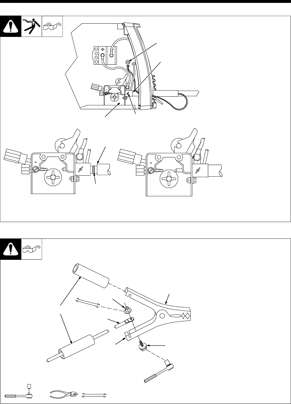
SECTION 5 − INSTALLATION
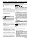
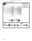
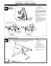
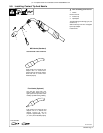
5-1. Installing Welding Gun
803 711-A
1 Drive Assembly
2 Gun Securing Thumbscrew
3 Gun End
Loosen thumbscrew. Insert end of
gun through opening in front
panel until it bottoms against
drive assembly. Tighten
thumbscrew.
Welding gun must be inserted
completely to prevent leakage of
shielding gas.
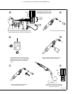
4 Gun Trigger Leads
Insert leads, one at a time, through
gun opening on front panel.
Connect female friction terminals to
matching male terminals in unit.
Polarity is not important.
Close door.
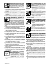
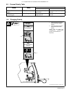
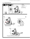
4
12
3
Correct
Incorrect
. Be sure that gun end is tight
against drive assembly.
3
Gun Fully Seated
3
Gun Not Seated
Exposed O-rings
will cause shielding
gas leakage.
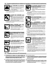
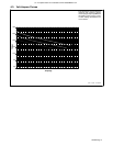
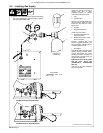
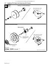
5-2. Installing Work Clamp
1 Nut
2 Work Cable From Unit
3 Work Clamp
4 Screw
5 Work Clamp Tabs
Bend tabs around work cable.
6 Insulating Sleeves
Slide one insulating sleeve over
work cable before connecting to
clamp.
Slide both insulating sleeves over
handles.
802 456-A
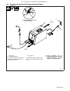
. Connection hardware must be tightened with proper tools. Do not just
hand tighten hardware. A loose electrical connection will cause poor weld
performance and excessive heating of the work clamp.
Tools Needed:
7/16 in
7/16 in
1
2
3
4
5
6