


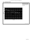
. A complete Parts List is available at www.HobartWelders.com
OM-925 Page 14
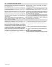
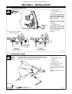
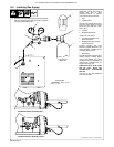
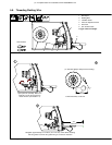
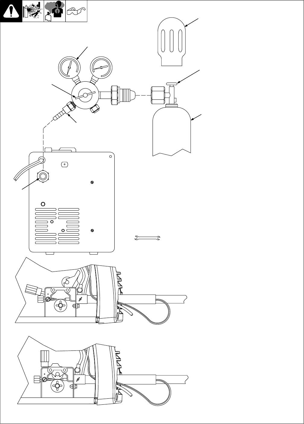
5-5. Installing Gas Supply
Obtain gas cylinder and chain to
running gear, wall, or other
stationary support so cylinder
cannot fall and break off valve.
1 Cap
2 Cylinder Valve
Remove cap, stand to side of valve,
and open valve slightly. Gas flow
blows dust and dirt from valve.
Close valve.
3 Cylinder
4 Regulator/Flowmeter
Install so face is vertical.
5 Regulator/Flowmeter Gas
Hose Connection
6 Welding Power Source Gas
Hose Connection
Connect supplied gas hose
between regulator/flowmeter gas
hose connection, and fitting on rear
of welding power source.
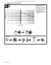
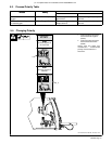
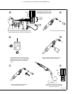
7 Flow Adjust
Flow rate should be set when gas is
flowing through welding power
source and welding gun. Open
feedhead pressure assembly so
that wire will not feed. Press gun
trigger to start gas flow.
Typical flow rate is 20 cfh (cubic
feet per hour). Check wire
manufacturer’s recommended
flow rate.
After flow is set, close feedhead
pressure assembly.
Tools Needed:
Ref. 804 654-A / 802 441 / Ref. 804 623-A
5/8, 1-1/8 in
6
Argon Gas Or
Mixed Gas
. DO NOT use Argon/Mixed gas regulator/flowmeter
with CO
2
shielding gas. See Parts List for optional
CO
2
gas regulator/flowmeter.
Feedhead Pressure Assembly Open
Feedhead Pressure Assembly Closed
1
2
3
4
5
7